- Cut a 3-inch (76mm) piece of magnet wire. Cut the remaining piece in half.
- Using the included sandpaper, scuff approximately ½ inch (12mm) of insulation from both ends of each of the two longer paddle wires.
- For the short 3-inch wire, scuff 2 inches (51mm) of insulation from one end only.
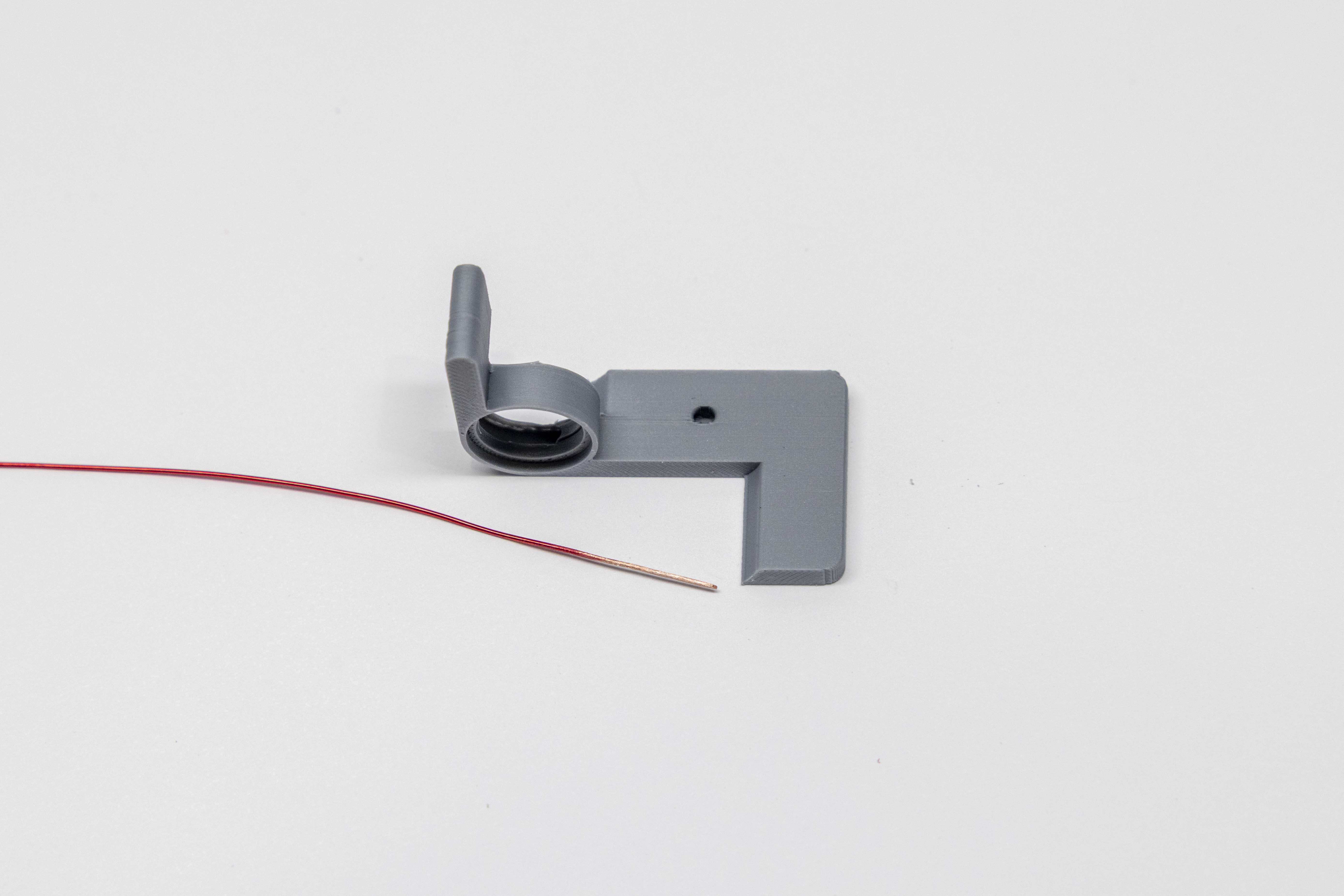
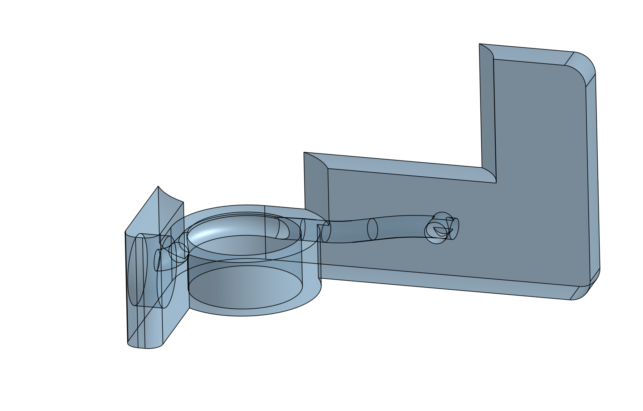
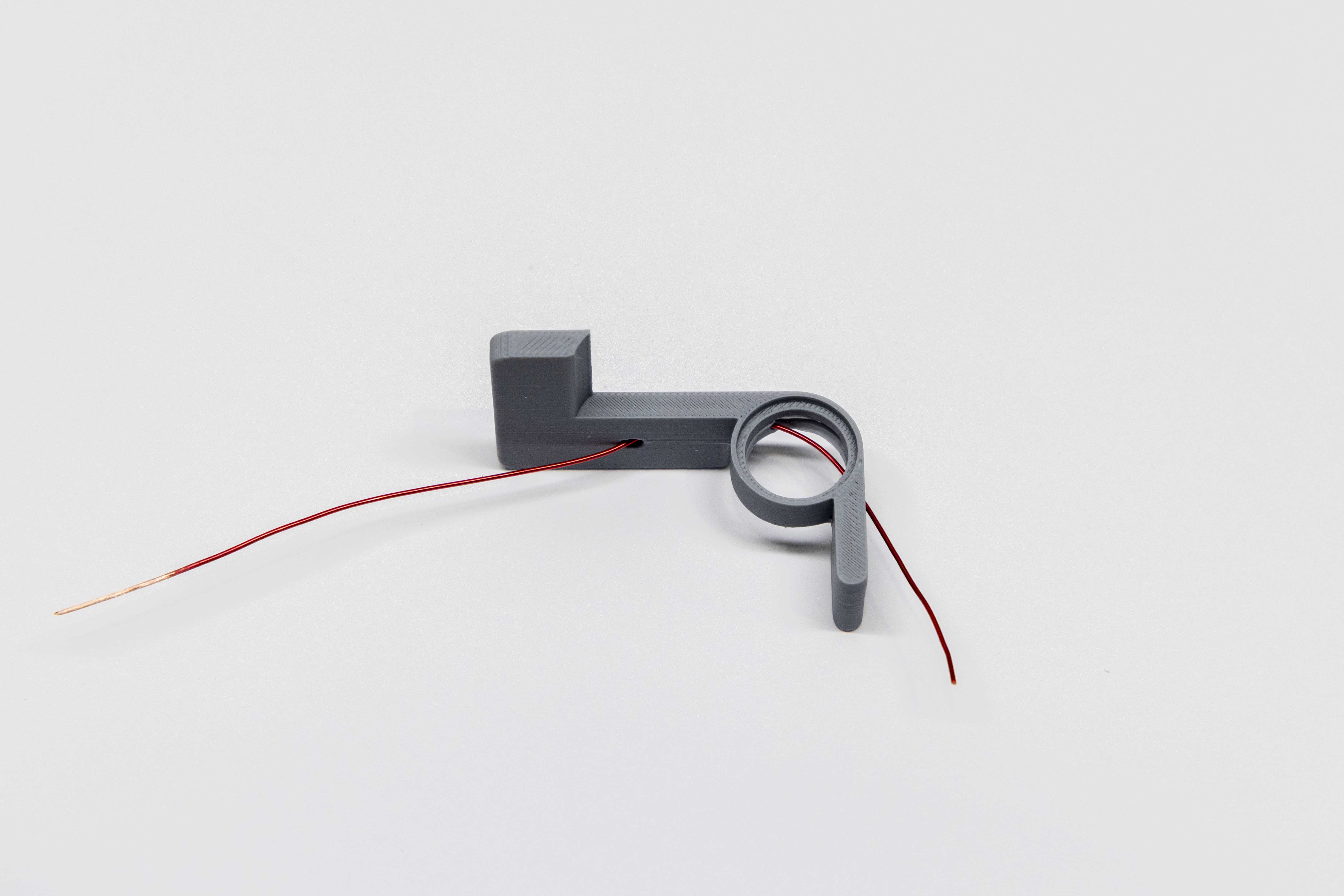
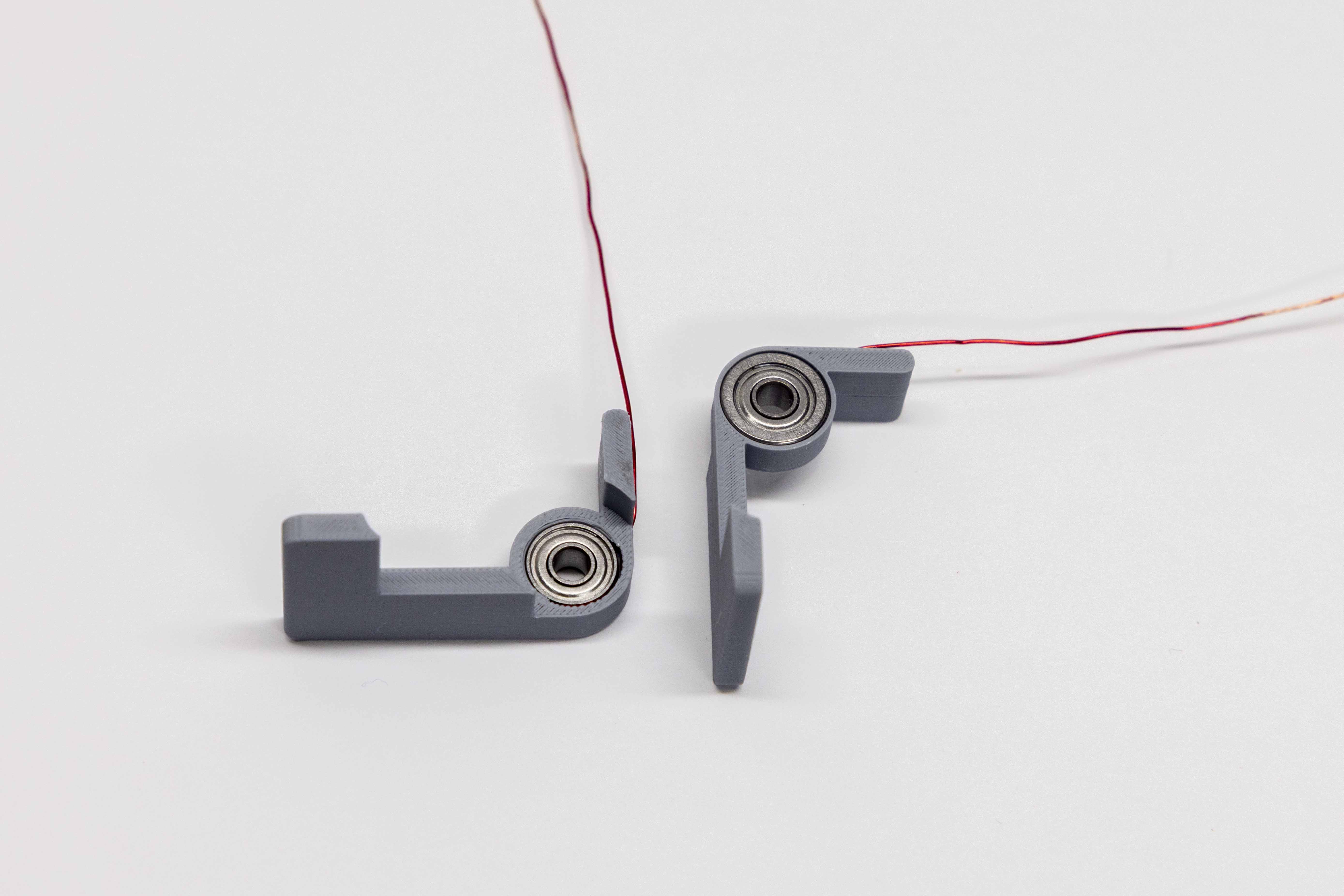
- Feed the wire through the paddle starting from the paddle arm, feeding toward the bearing ring.
- Use needle-nose pliers to grab the end and thread the wire through the second hole at the back near the magnet cavity.
- Repeat for the second paddle.
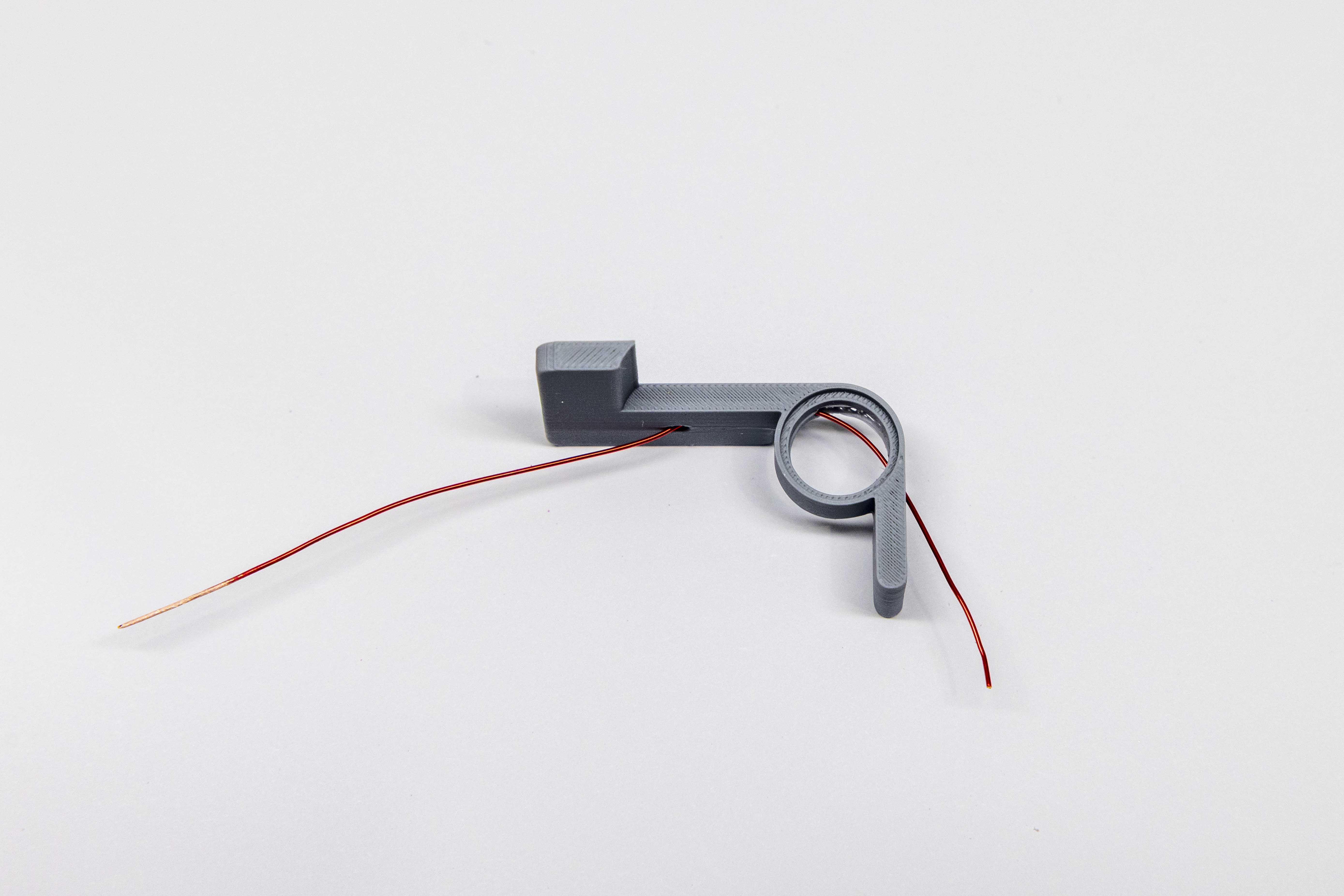
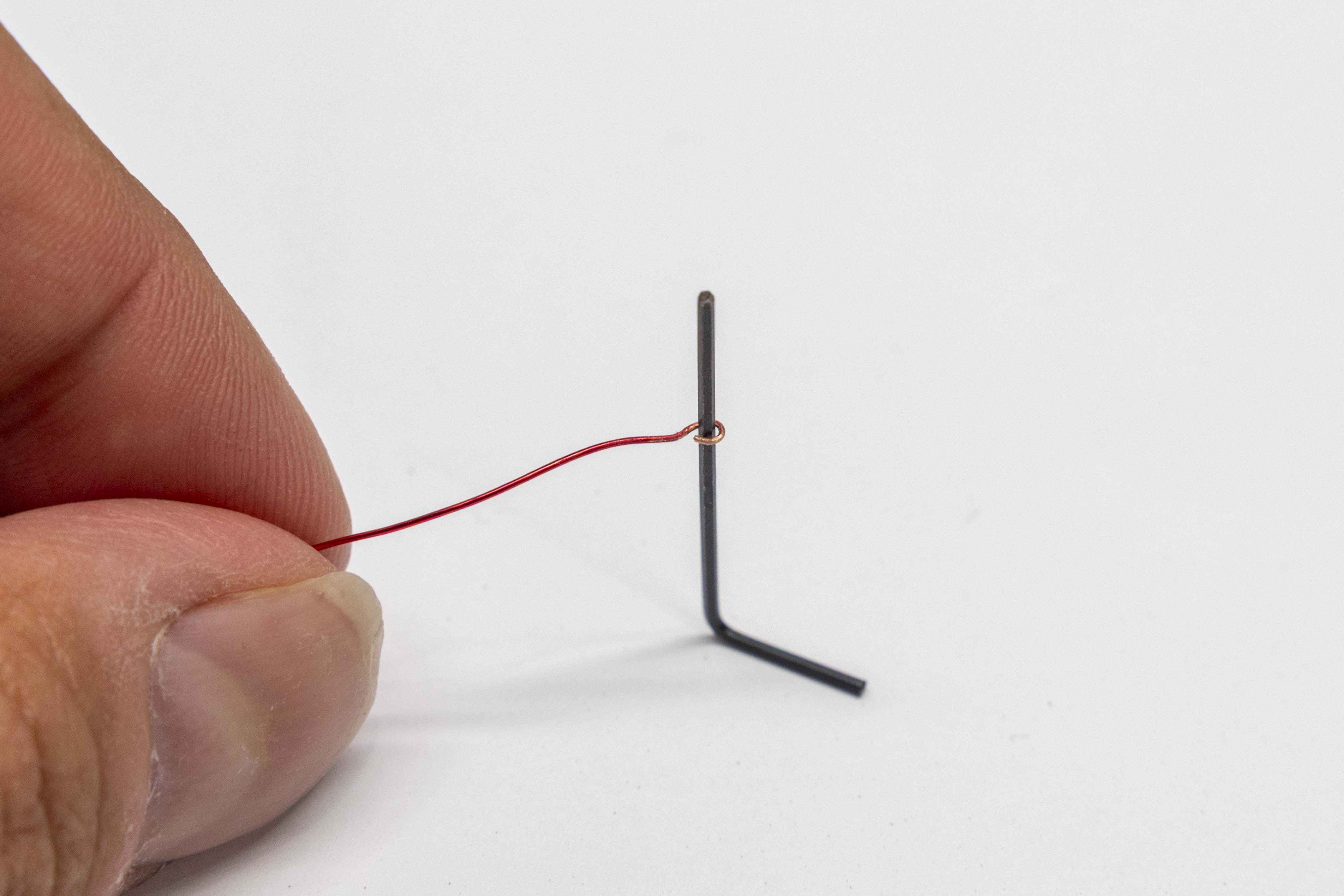
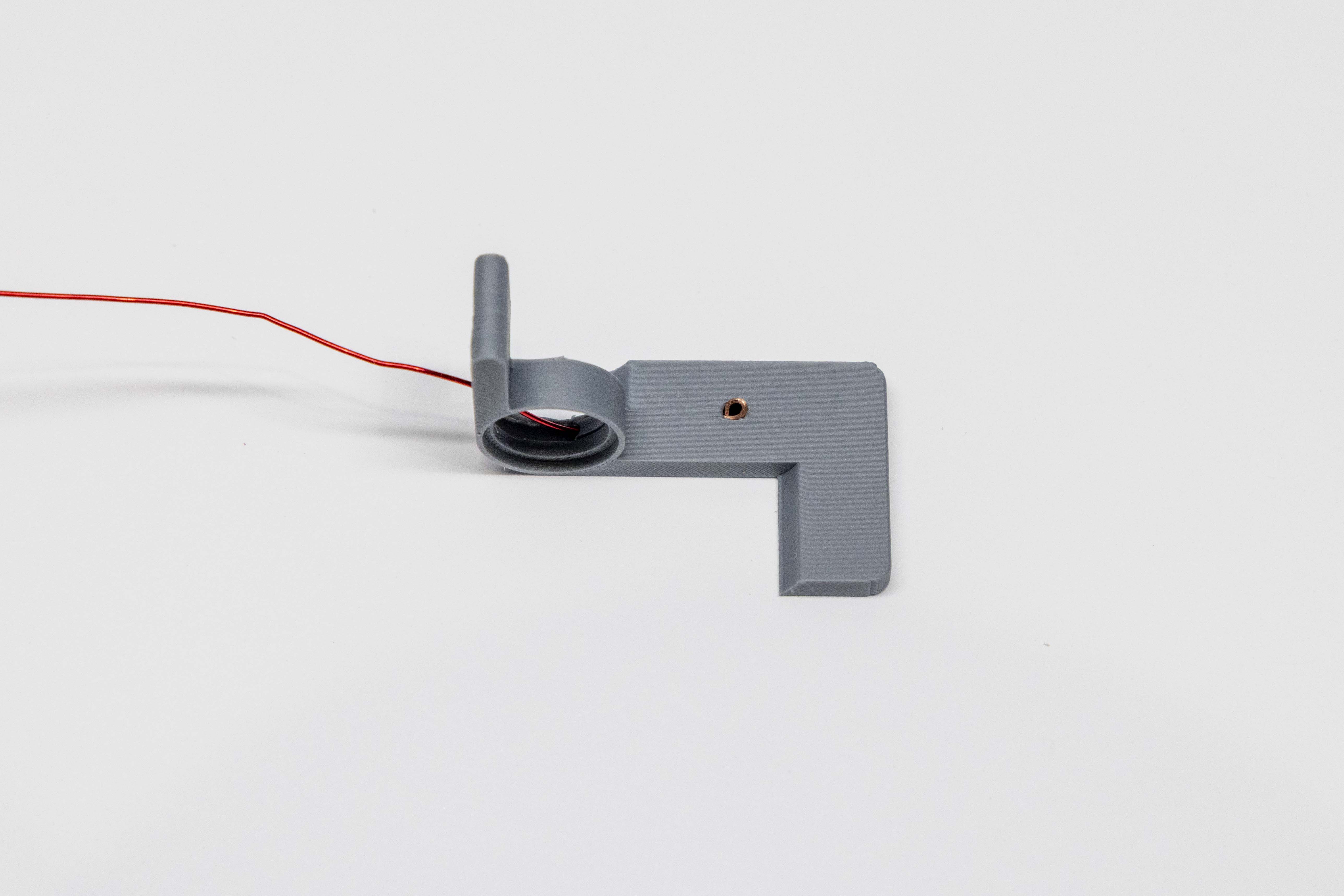
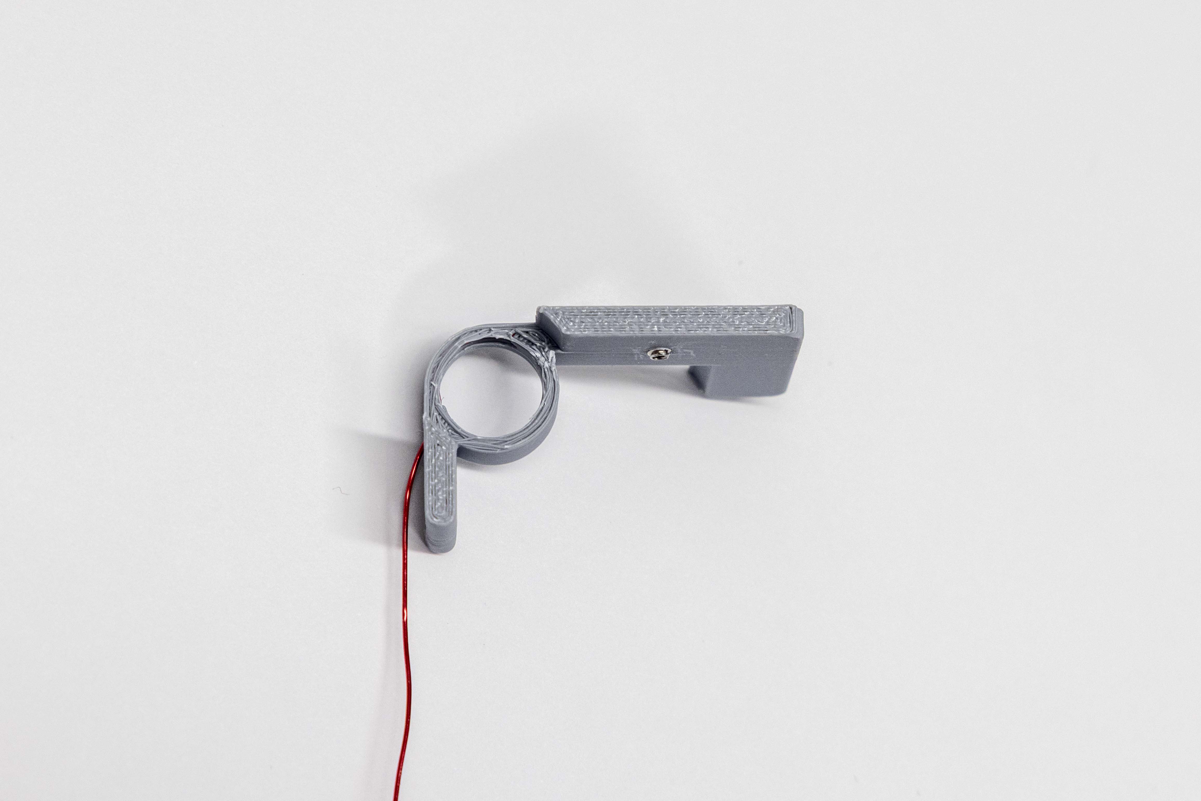
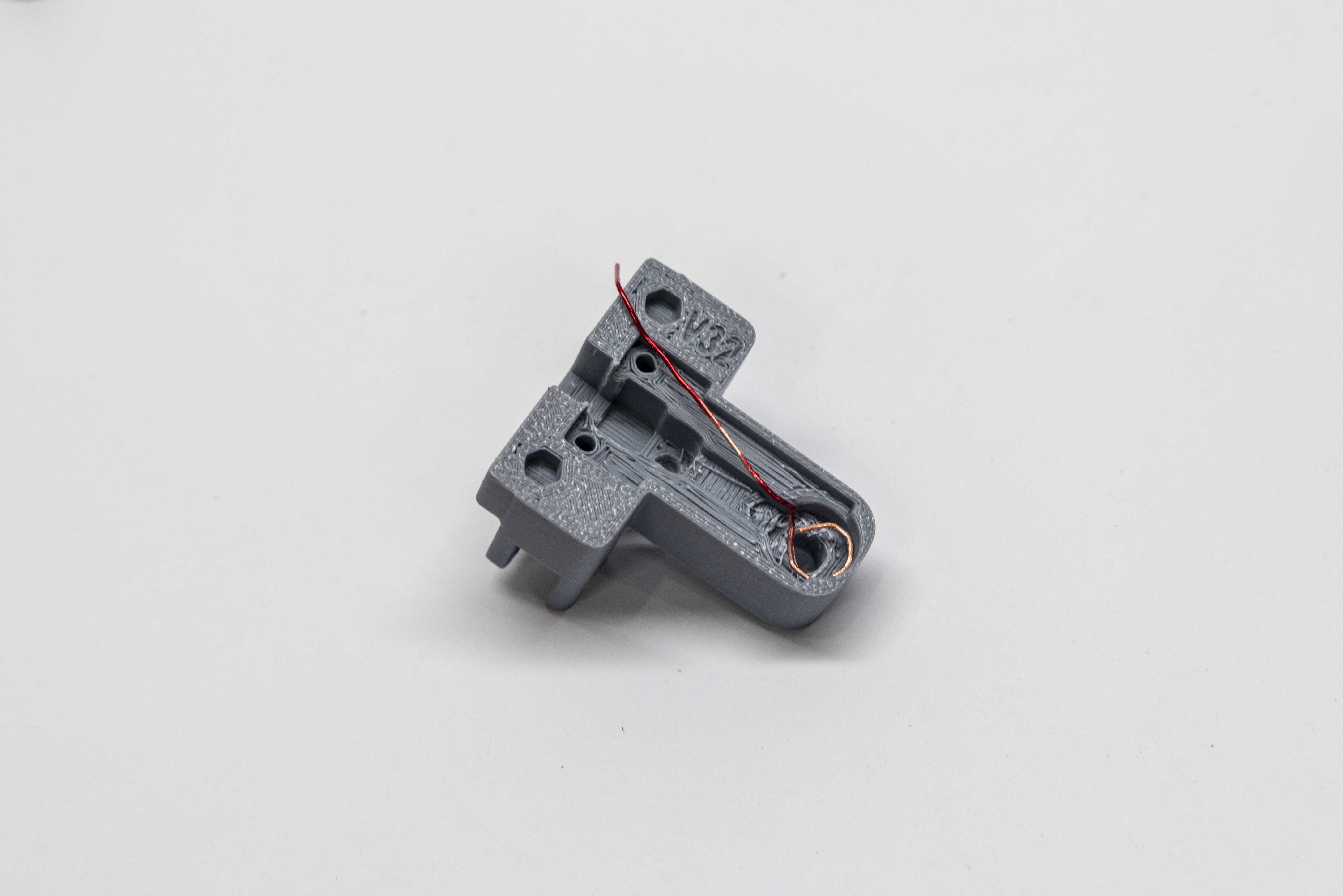
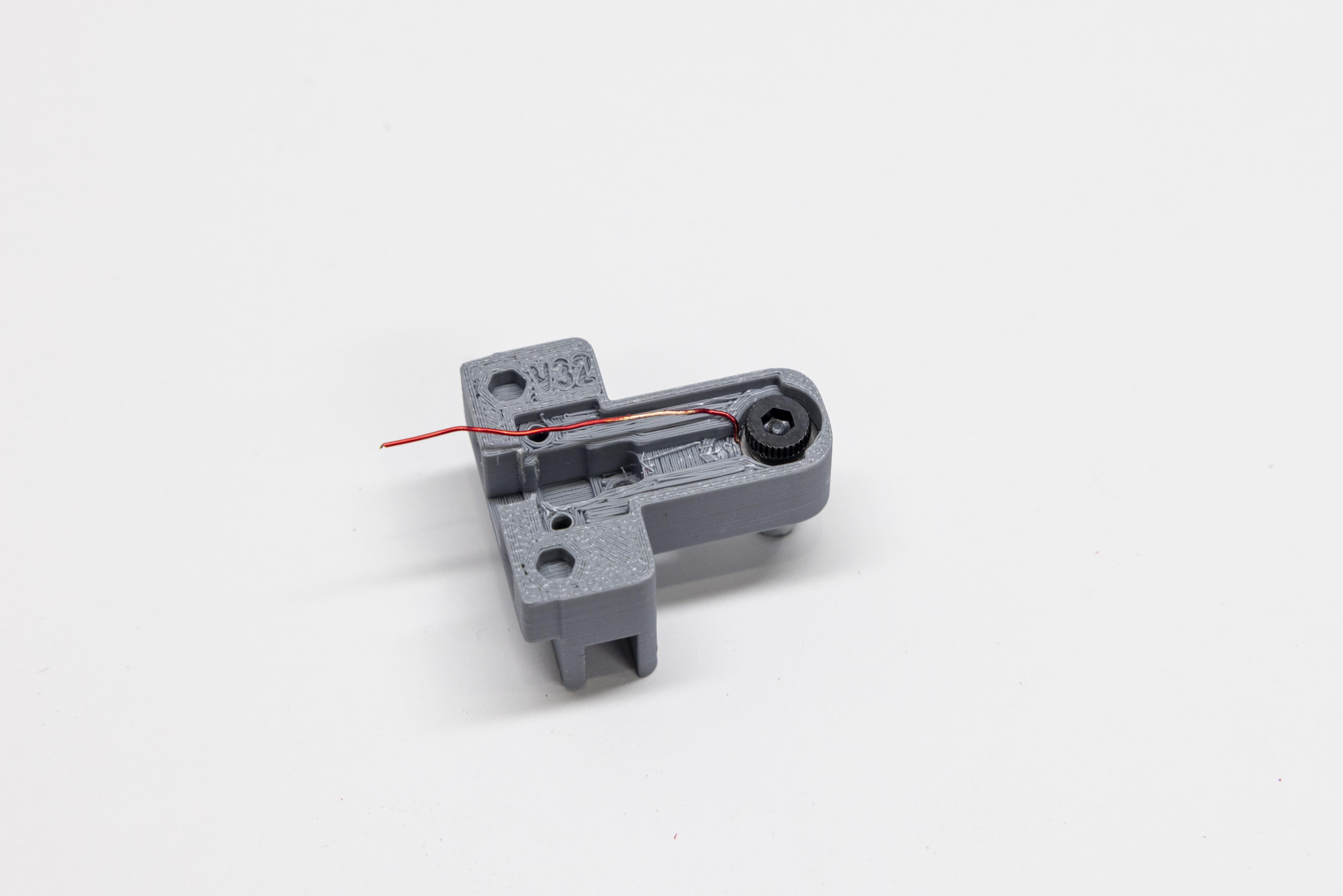
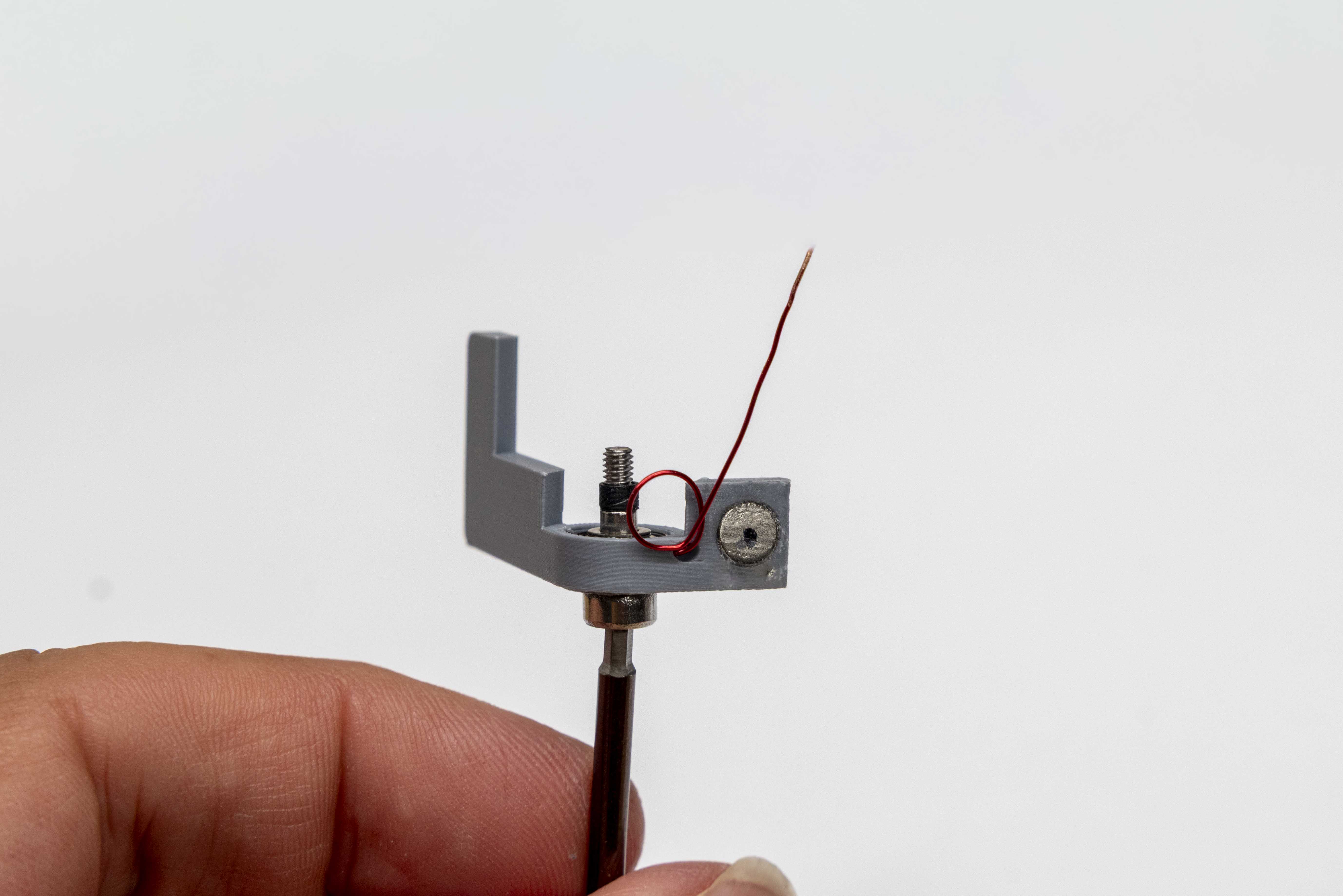
- Using the 0.9mm hex key as a mandrel, form a small loop at the paddle arm end of the wire — this is the end opposite the magnets and bearings.
- Verify the loop does not overlap itself at any point. A single, clean layer ensures consistent seating depth. See reference image.
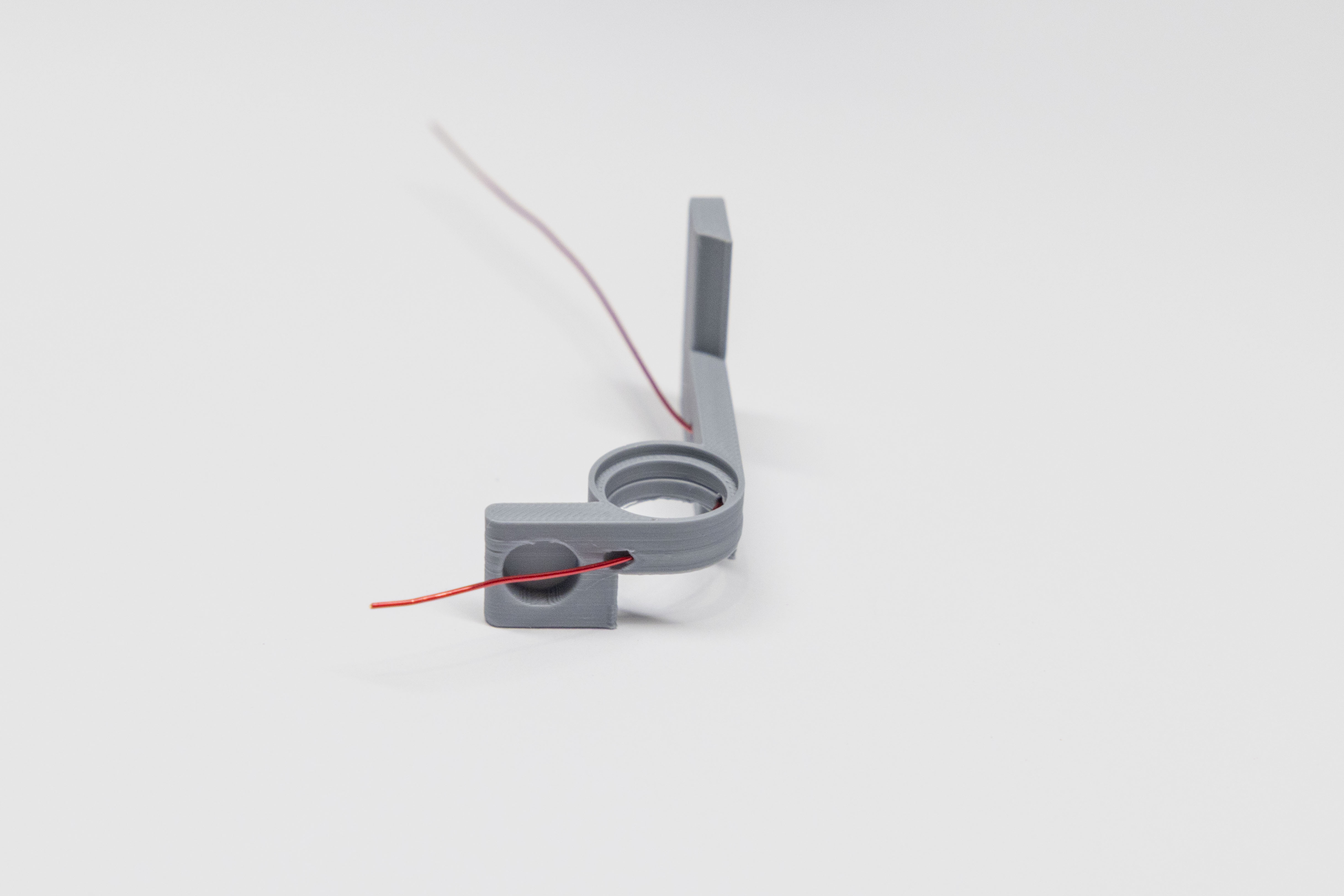
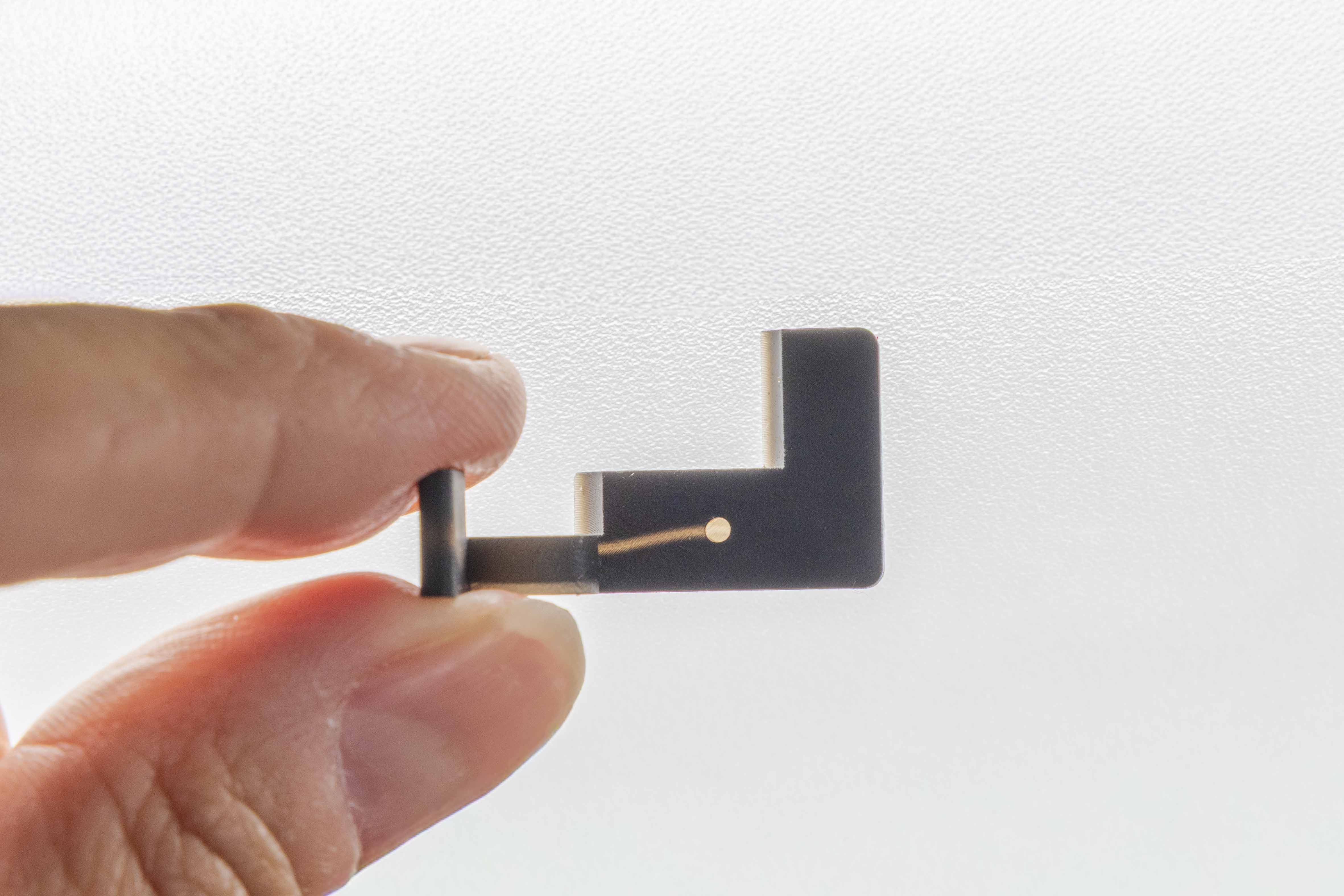
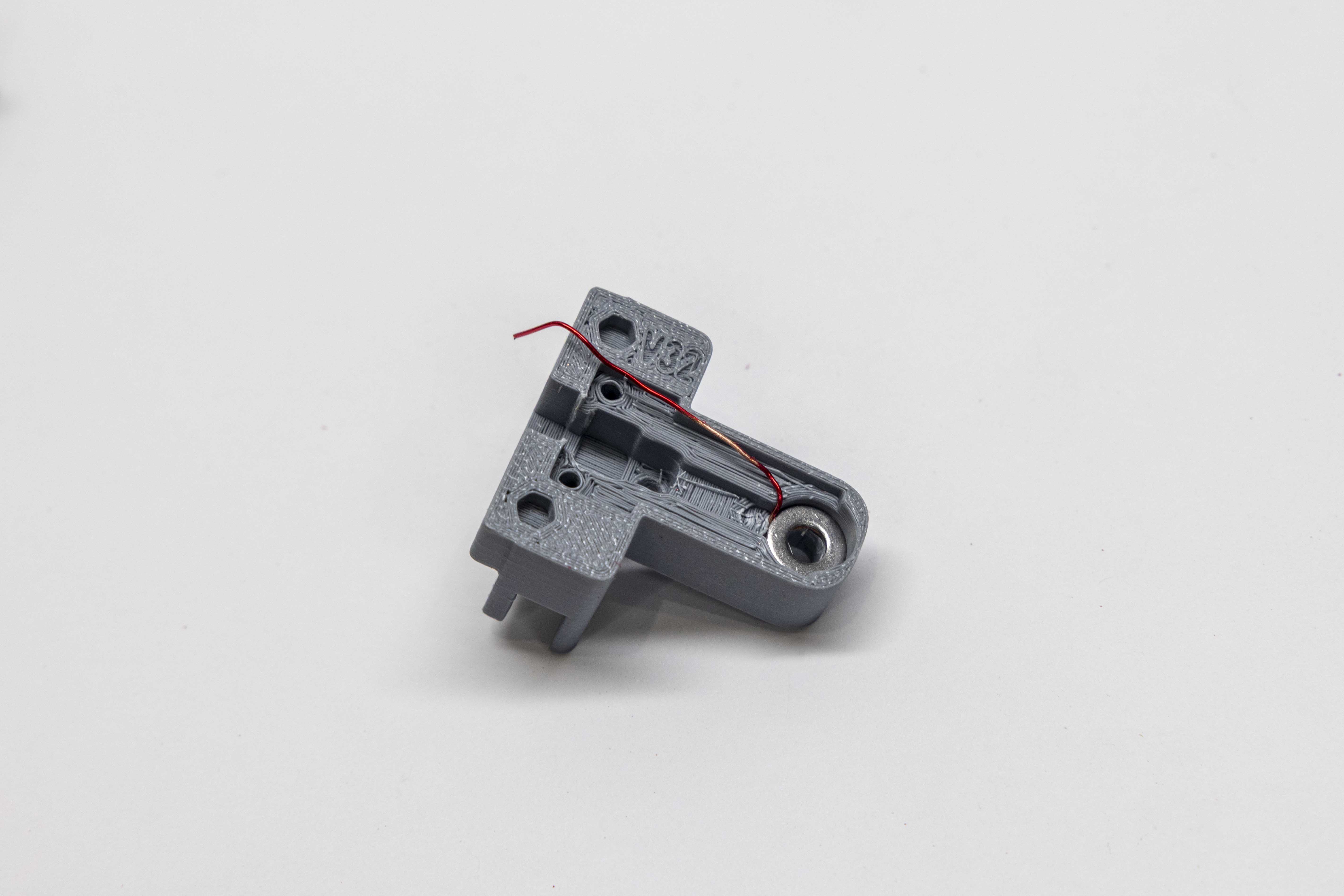
- Gently pull the loose end of the wire through the paddle arm until the loop meets the opening of the wiring hole.
- The wire may need to be rotated so that the loop rests flat against the bottom of the hole. Using the tip of the 0.9mm hex tool, press the loop firmly down into the wiring hole until it is fully seated. See reference image.
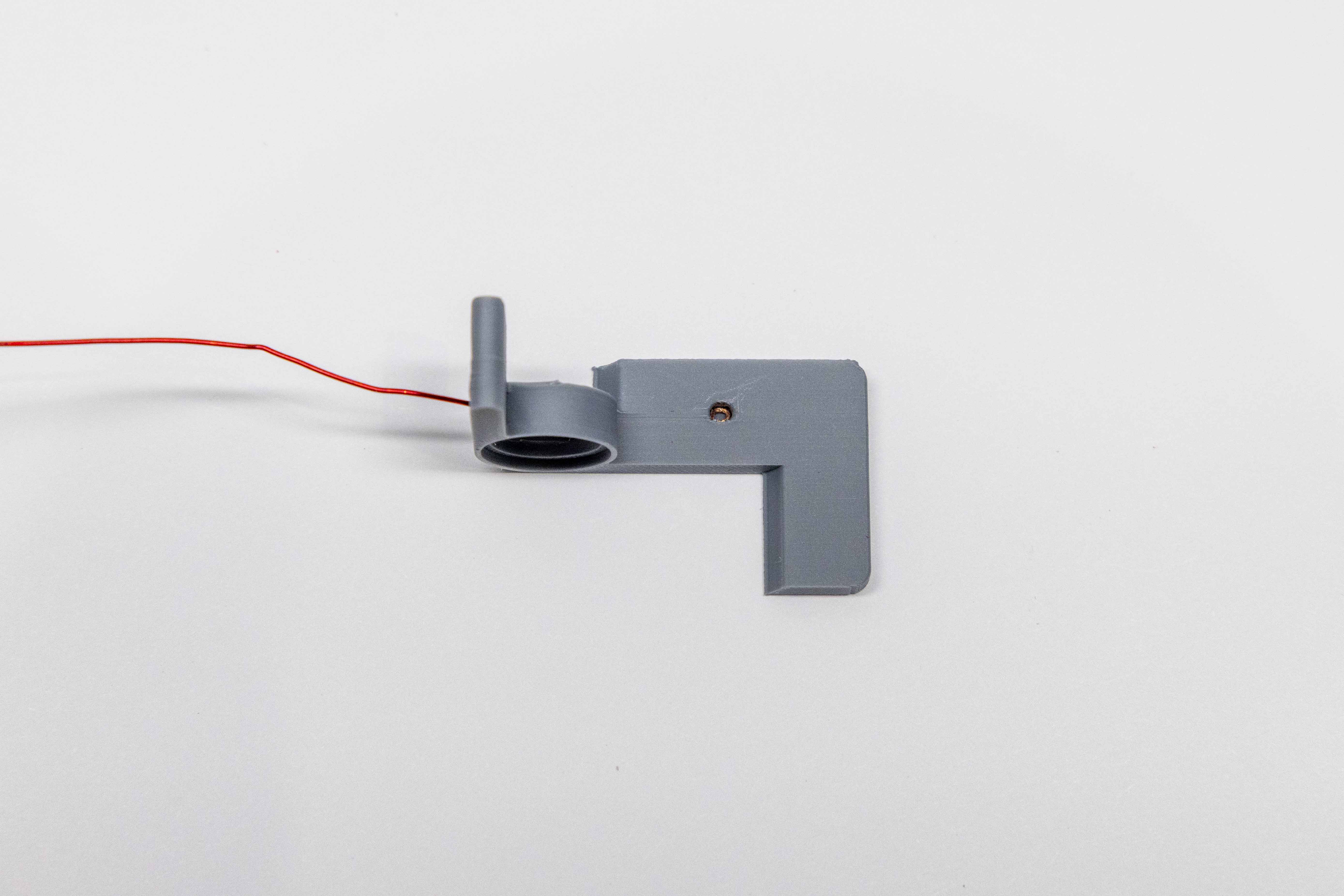
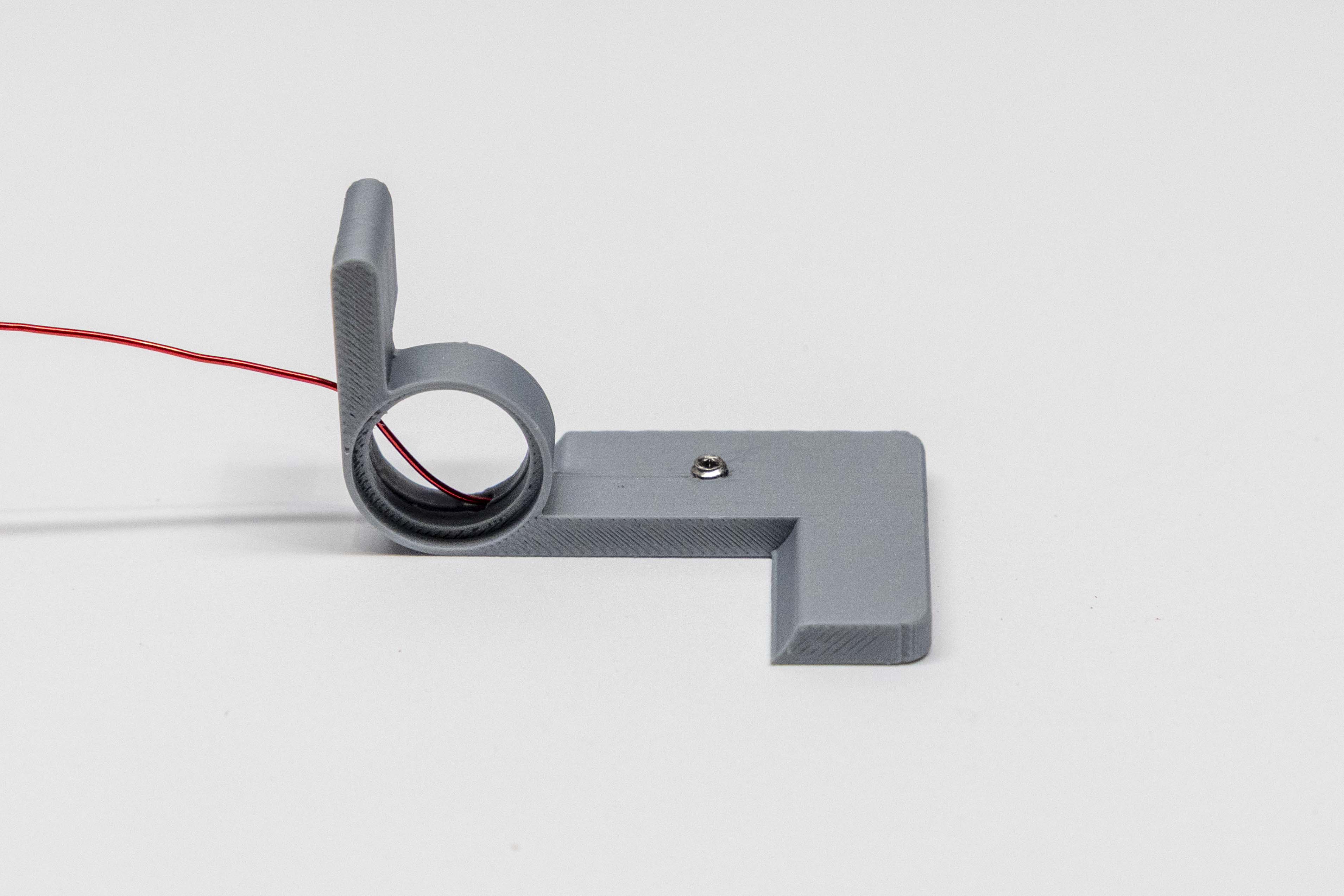
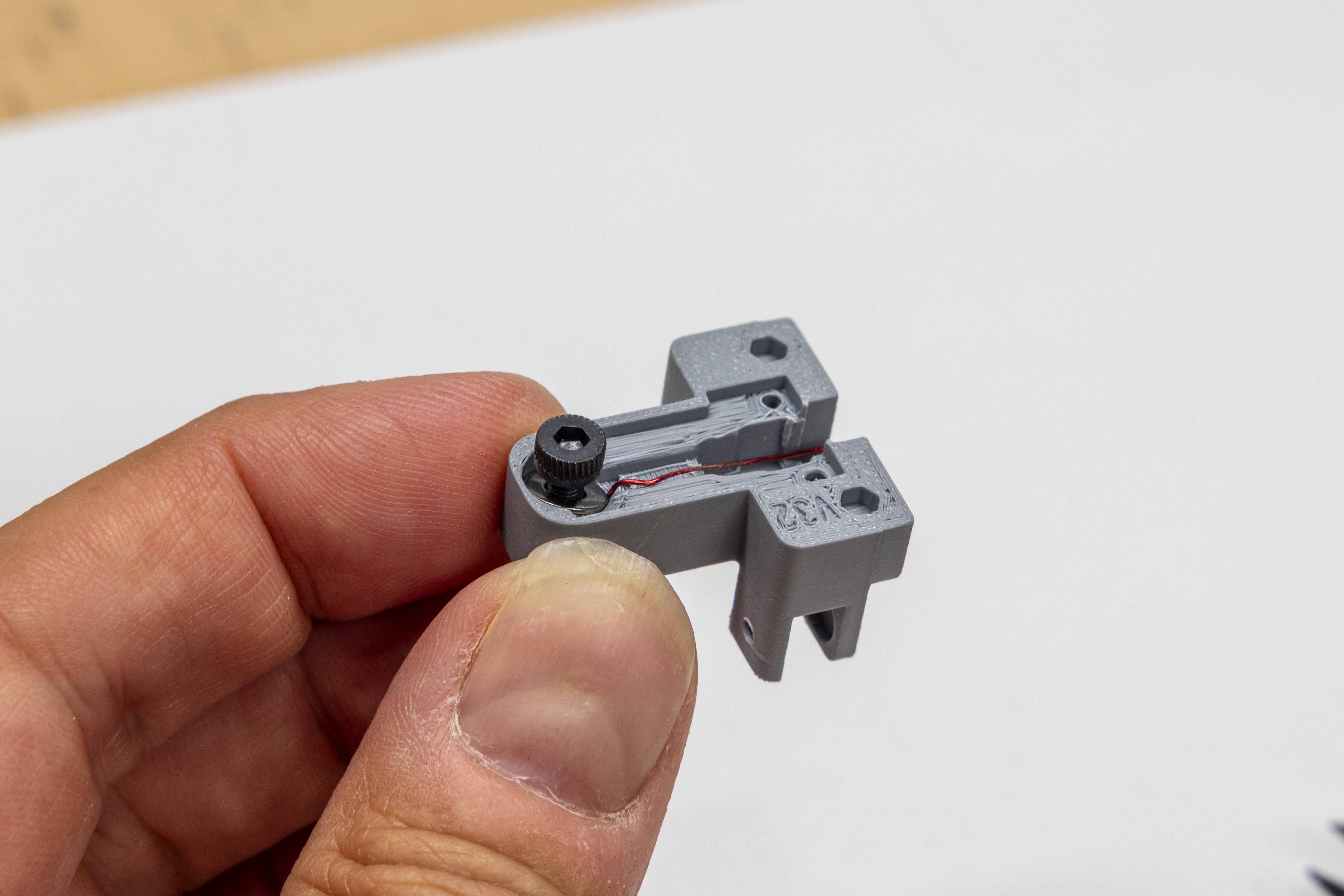
- Use the 0.9mm hex tool to insert an M2×2mm stainless set screw into the paddle wiring hole and thread it in. Tighten the set screw exactly 3 and 1/8 turns to snug it against the wire loop. Do not overtighten past 3 and 1/8 turns. Pro Tip: Rather than counting turns of the hex tool, it's easier to press the hex tool down firmly onto the set screw and rotate the paddle itself counter-clockwise 3 and 1/8 turns.
- Calibration: The set screw will sit slightly lower than the 0.5mm feeler gauge shelf. With the gauge resting in place, press lightly with your fingertip — you should not feel the set screw beneath it.
Perform the following steps for both paddles.
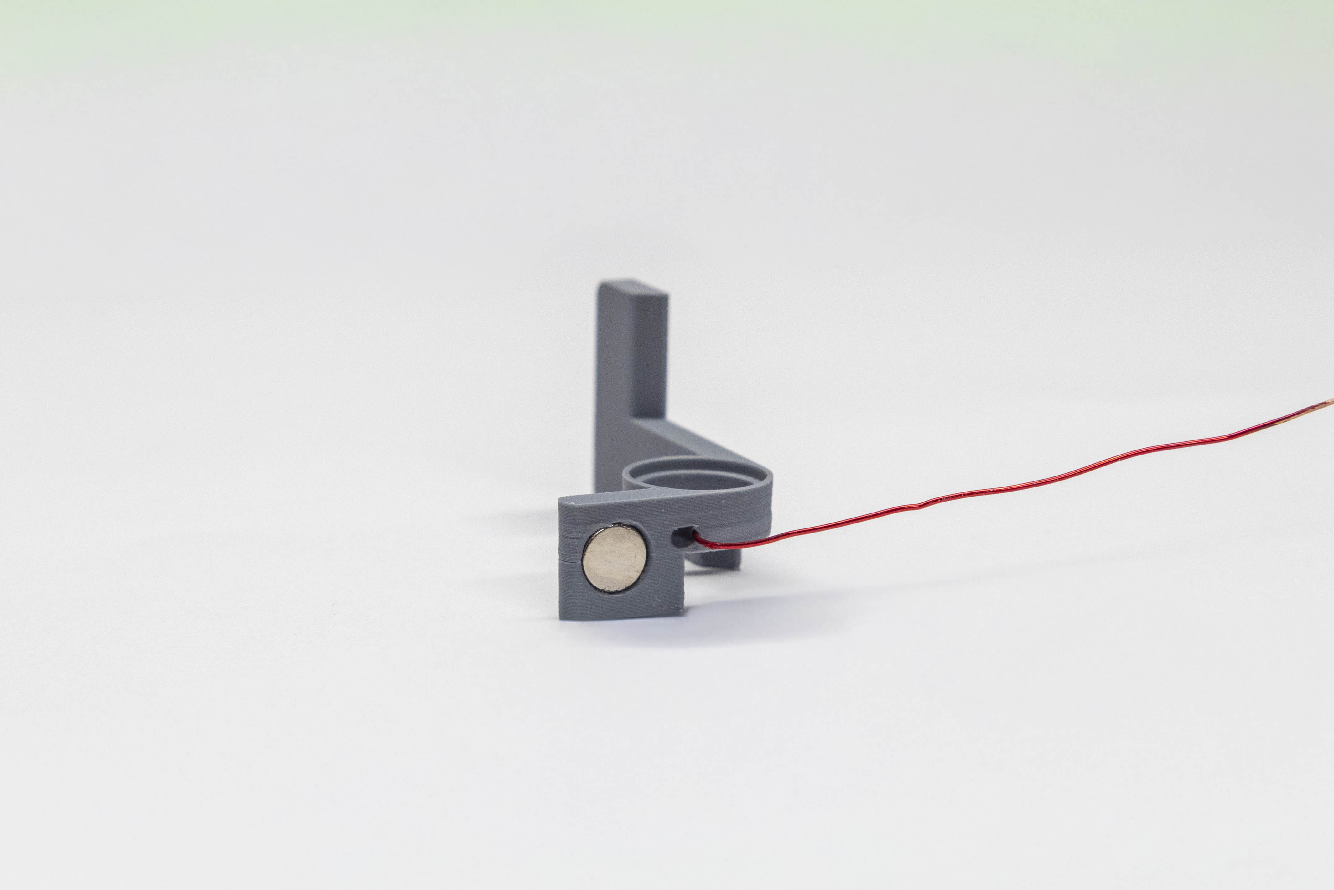
- Before applying glue, dispense a small amount onto a scrap surface (paper, cardboard, etc.) and confirm it flows as a gel — not a runny liquid. If it runs freely, do not use it on this step; the fit is tight and excess glue can foul the bore. Using a toothpick or other small pointy applicator, pick up a tiny dab and place it into each magnet hole.
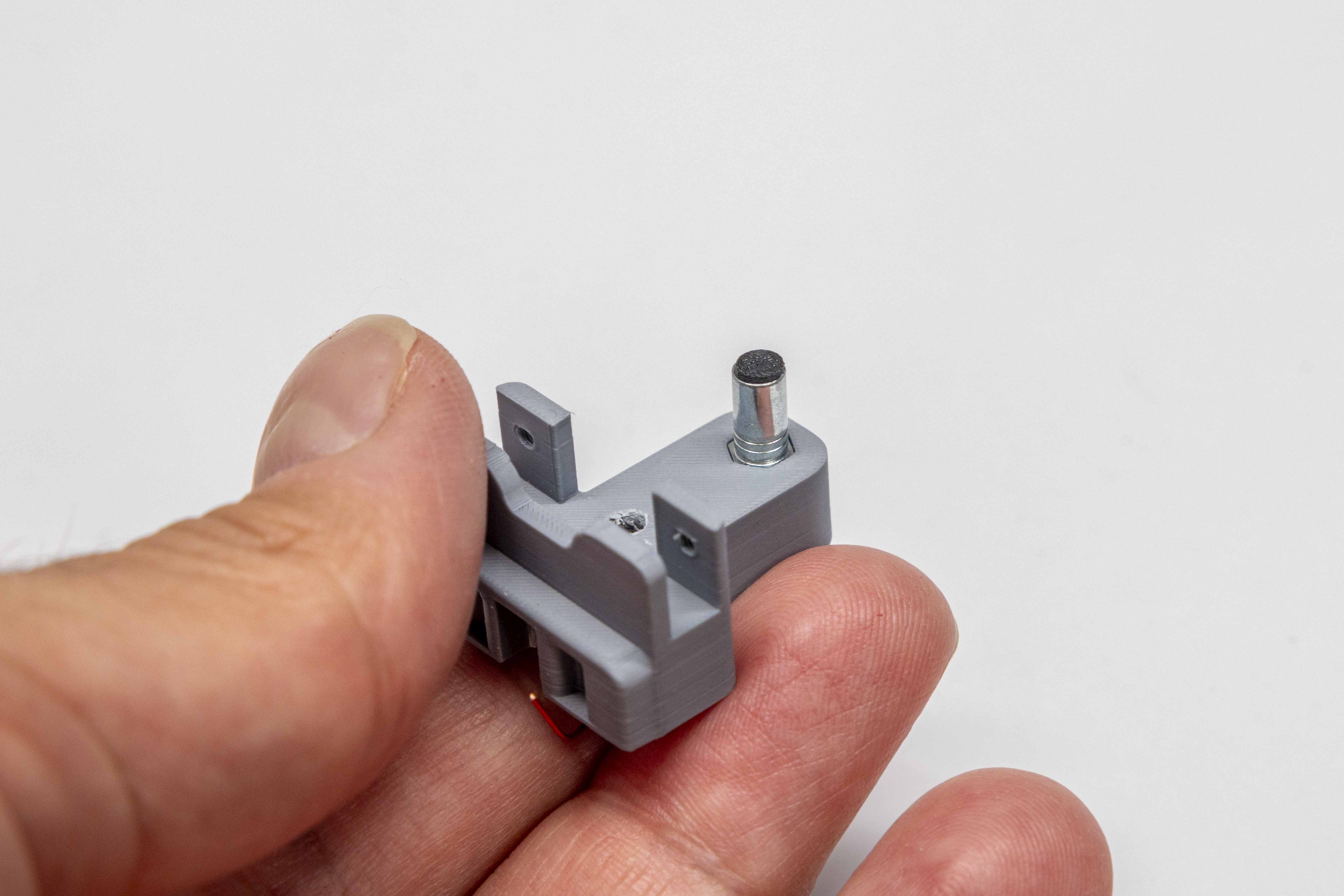
- Using your fingers or a non-metallic tool, press the 5×2mm magnets into the holes until flush. Wipe away any glue that squeezes out before it cures.
- For each paddle, guide the magnet wire into the small channel cut into the wall of the bearing bore. Check from above: when looking straight down into the bore, the wire should be fully nested in the channel and not visible. If any wire is visible across the opening, press it further into the channel before proceeding. A wire that is not fully seated will be pinched or cut when the bearing is pressed in.
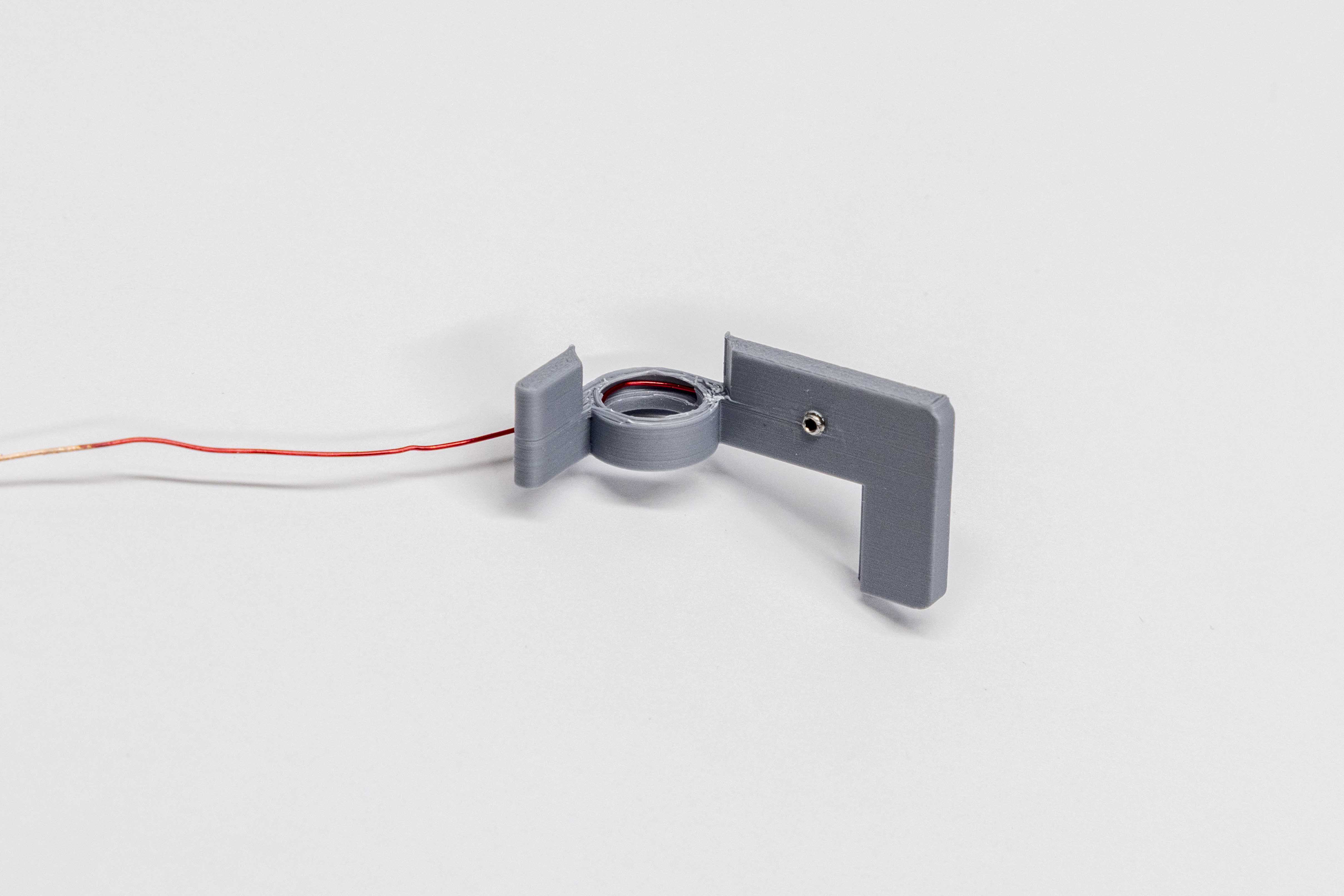
- Apply a light bead of glue along the flange shoulder of each bearing. Press each bearing fully into the paddle bore. Confirm the magnet wire is still seated in its cutout and not pinched. Wipe away any excess glue. Set both paddles aside to dry.
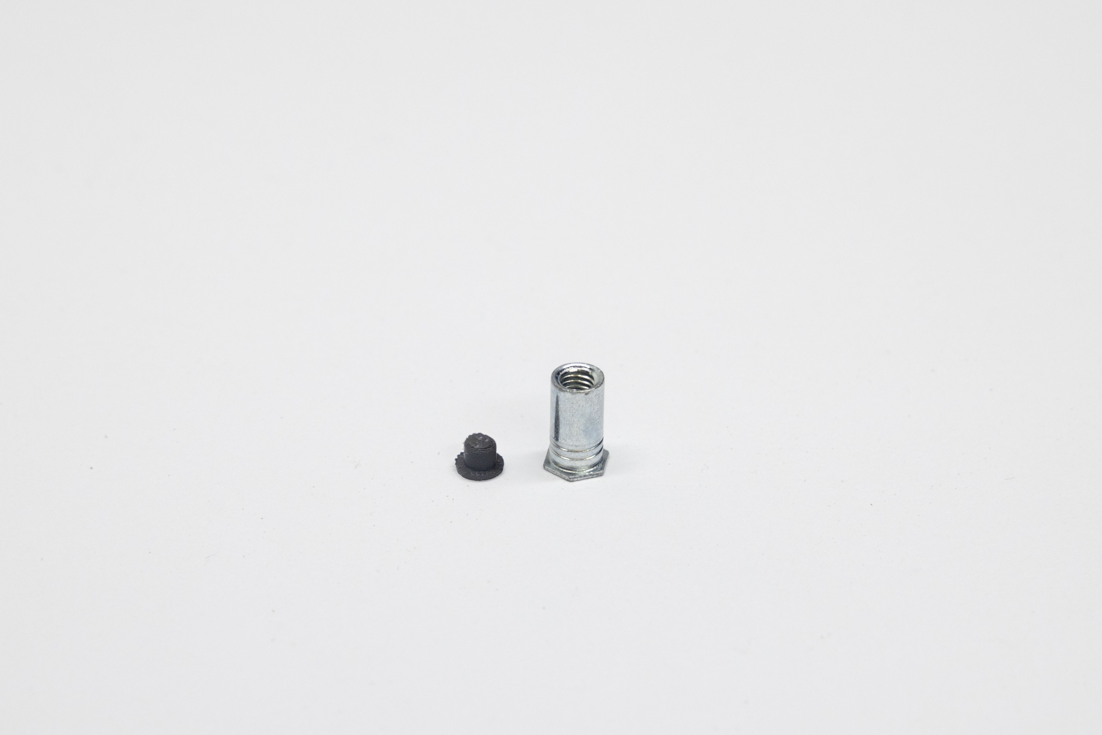
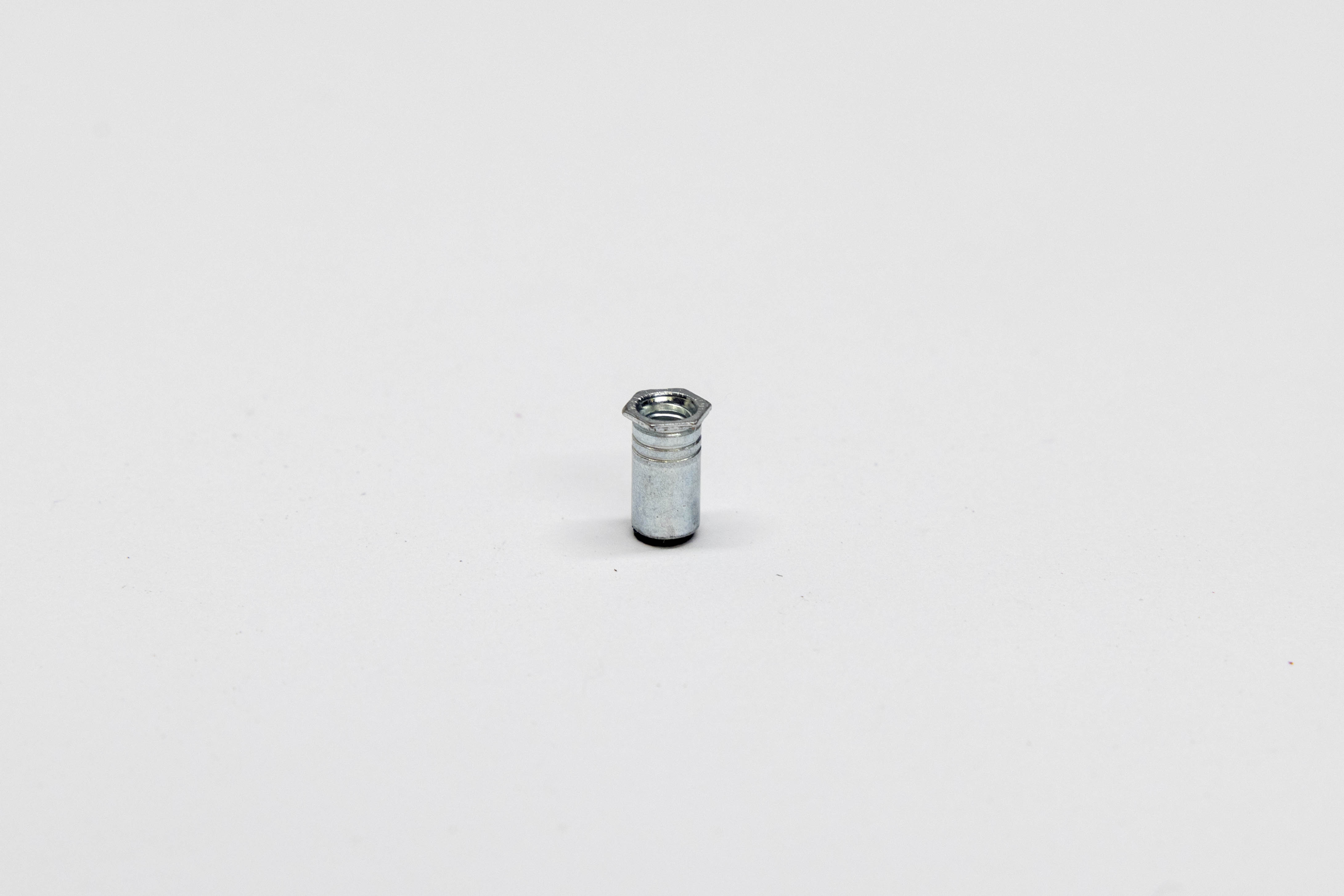
- Press-fit the M3 Standoff Cap (small stub nub) onto the round end of the M3×8mm standoff. Lay the nub flat on the workbench. Set the round end of the standoff down onto the nub and press firmly straight down — use a flat tool or a flat surface to apply even pressure. Keep the standoff perfectly vertical as you press; tilting it at an angle will prevent a secure fit.
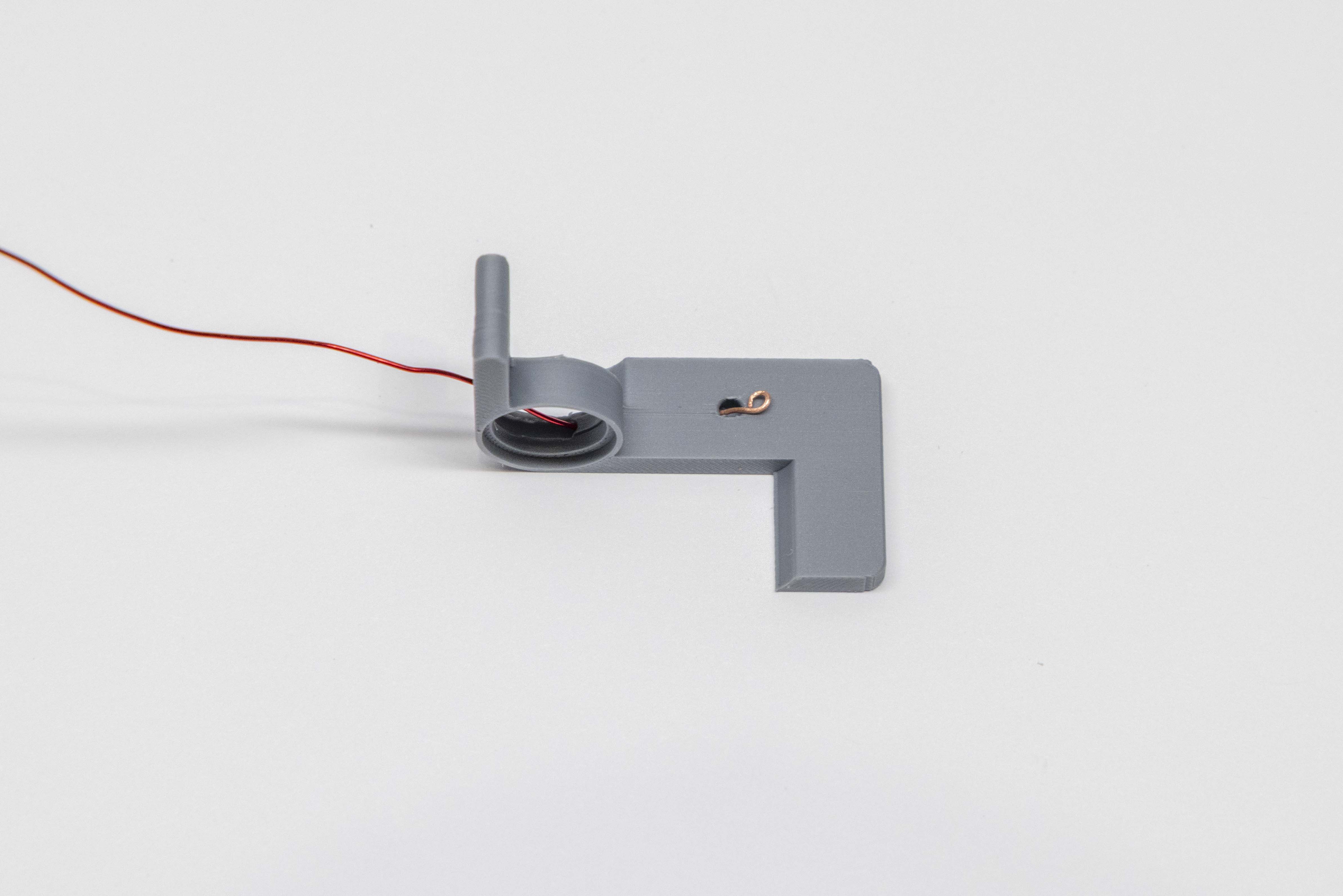
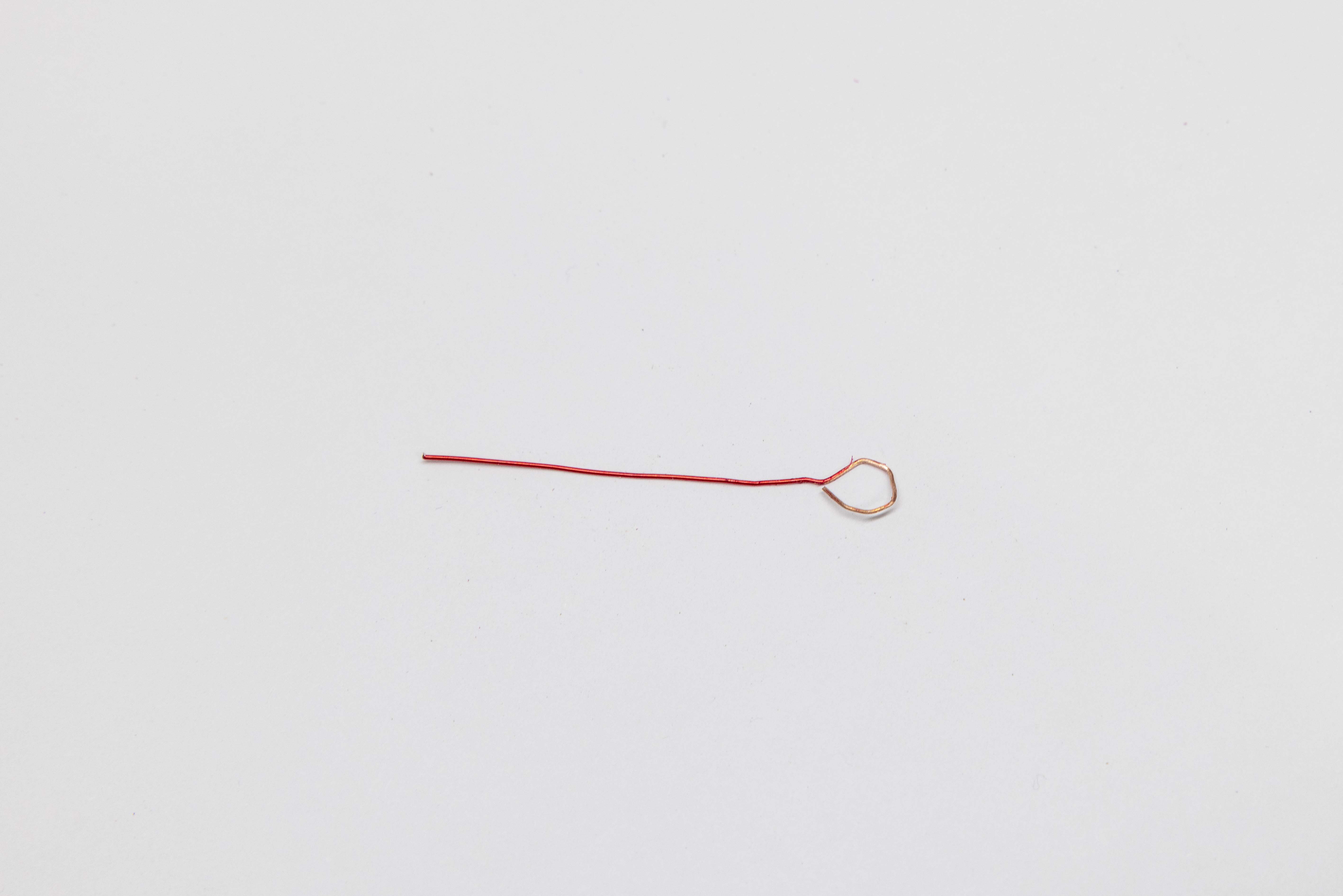
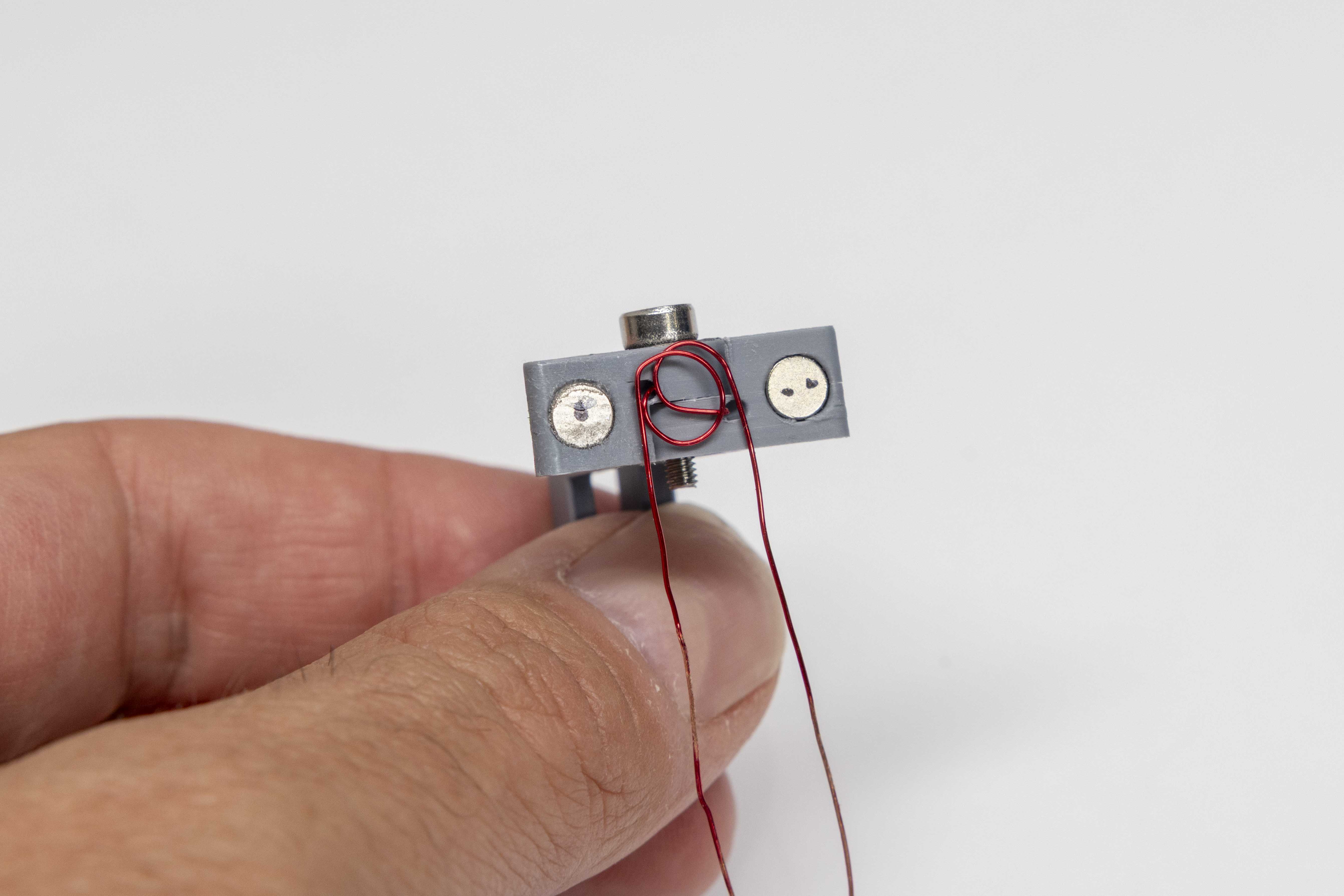
- Take the 3-inch piece of magnet wire set aside in Step 2 and form a 270° loop with the long scuffed end of the wire (see photos). Lay it flat in the cavity on the bottom of the key body. Route the wire tail toward the side of the key body — do not route it through the center. The center of the cavity must stay clear for the tension-fit stub on the key cap to seat properly.
- Set the M3 washer on top of the wire loop to hold it in the cavity.
- From the underside, seat the M3×8mm round standoff into the hex notch.
- Insert the M3×10mm screw from above, threading down through the wire loop and washer into the standoff. Tighten firmly — the screw threads directly into stainless steel and will hold securely.
The CW key's return action is driven entirely by magnetic repulsion — each paddle magnet is paired with a body magnet of opposing polarity, pushing the paddle back to center after each press.
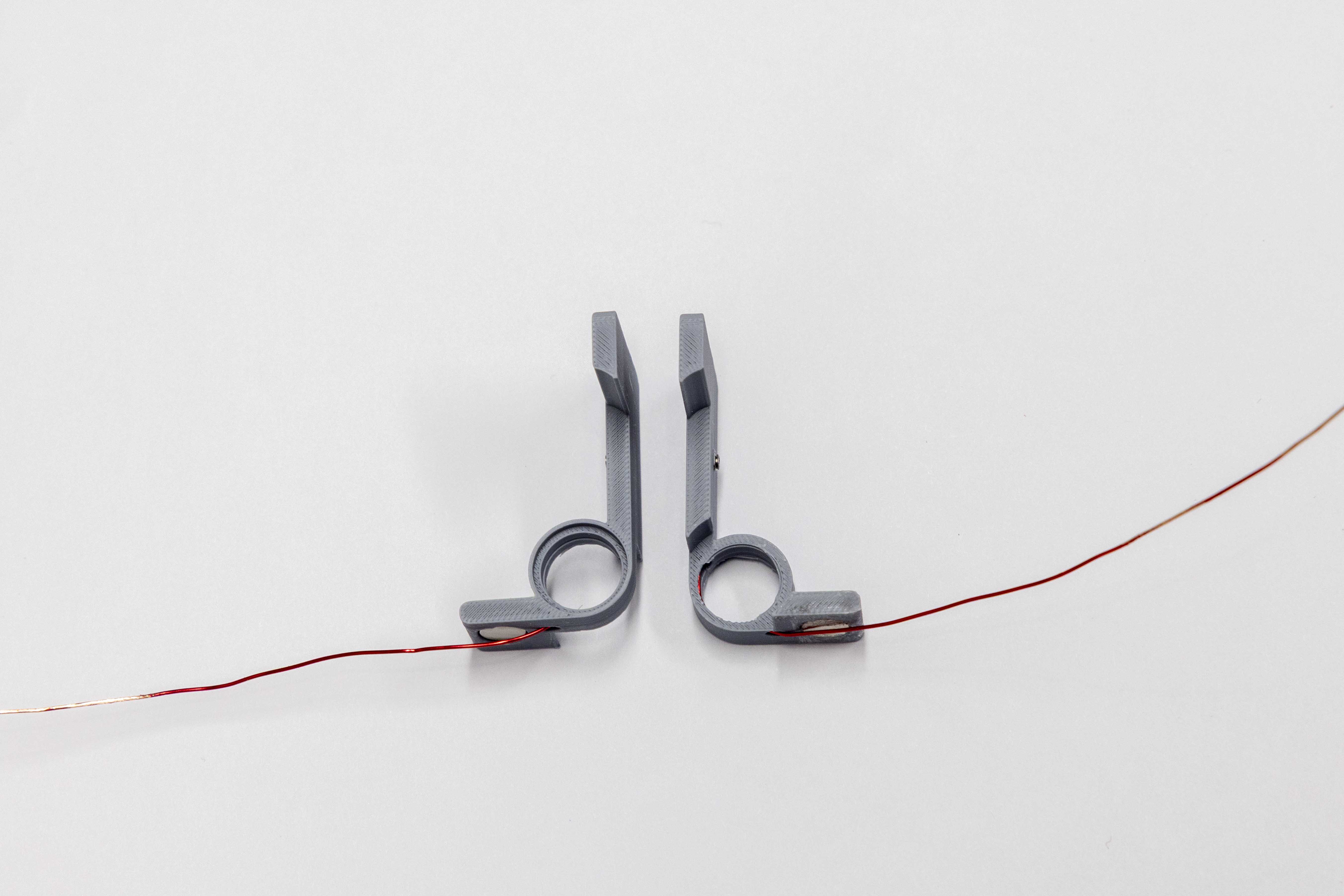
Part 1 — Identify Left and Right
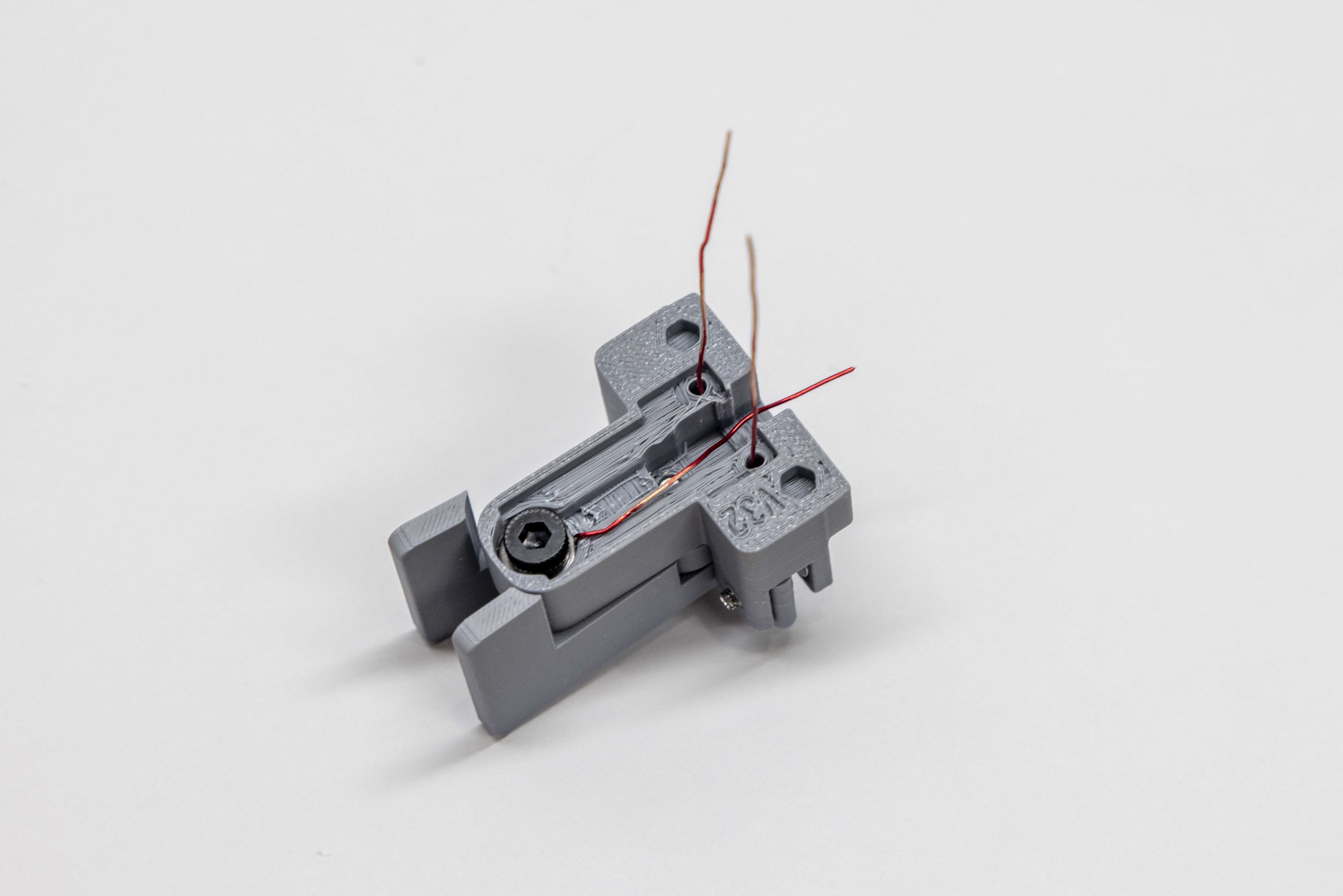
- Before handling any magnets, lay both paddles onto the key body in their installed position. Looking down from above, note which paddle sits on the left and which sits on the right. The left paddle is Paddle #1; the right paddle is Paddle #2. Set both paddles aside — this is your reference for the rest of the step.
Part 2 — Left Paddle (Paddle #1, one dot)
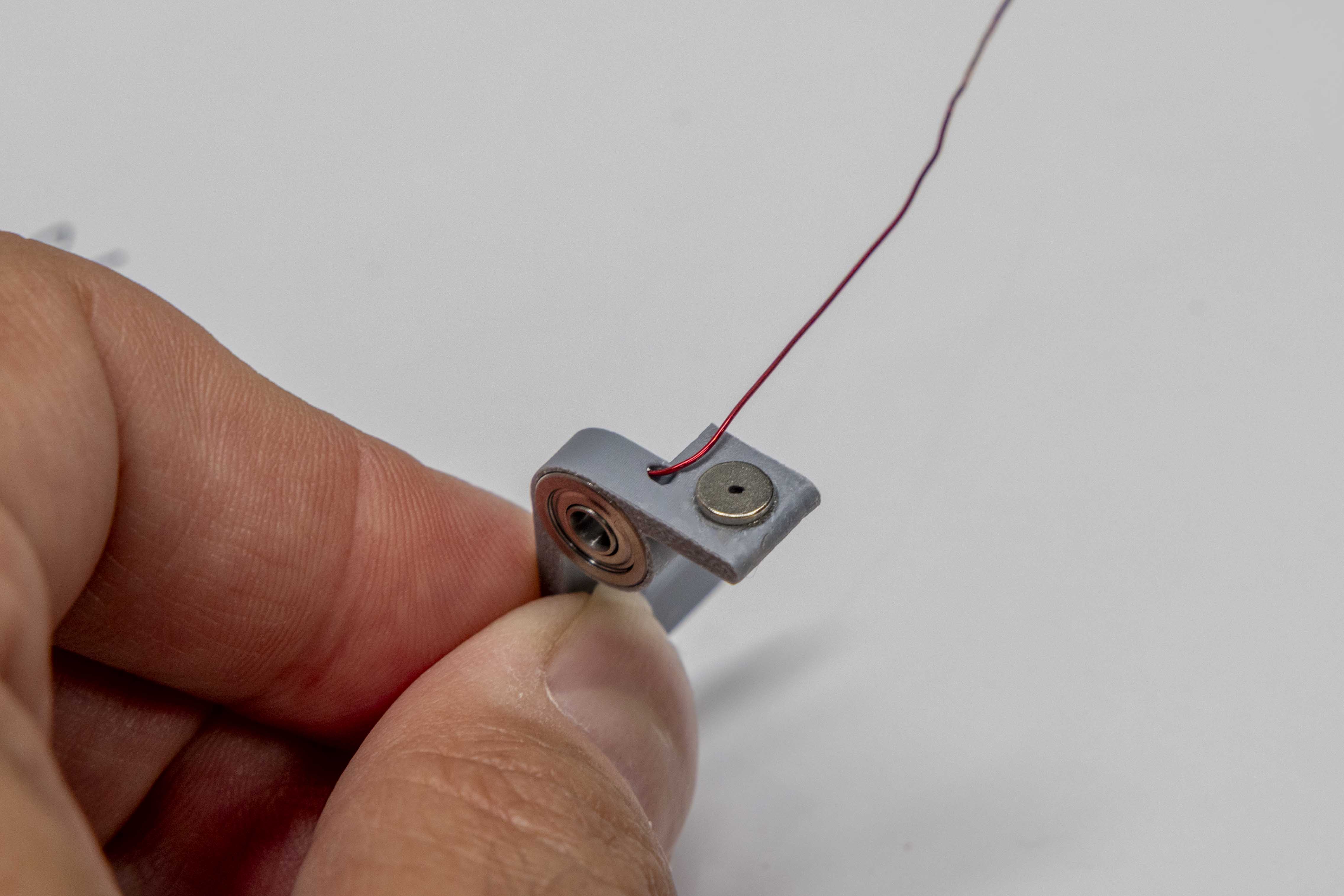
- Pick up the left paddle (Paddle #1). Hold a 5×1mm body magnet near its installed 5×2mm paddle magnet and allow it to attach freely — do not force or flip it. Let the magnet find its own attracted orientation.
- The Dot System: With the 5×1mm magnet still held against the paddle magnet, mark the face now pointing away from the paddle with one dot (•) using a fine-tip marker. This dotted face will face outward when the magnet is installed in the body.
- Apply a small dab of glue to the unmarked face of the 5×1mm magnet (the face with no dot). Press it, glue-side first, into the left body magnet hole — the hole that corresponds to Paddle #1's position on the key body. Using a non-metallic tool, press firmly until the magnet is fully flush. The dotted face must point outward. Wipe away any excess glue immediately. Note: The body magnet hole for Paddle #1 is on the opposite side of the key body from where Paddle #1 sits.
Part 3 — Right Paddle (Paddle #2, two dots)
- Pick up the right paddle (Paddle #2). Using a fresh 5×1mm magnet, repeat the same process: hold it near the 5×2mm paddle magnet and let it attach freely. Mark the outward-facing face with two dots (••).
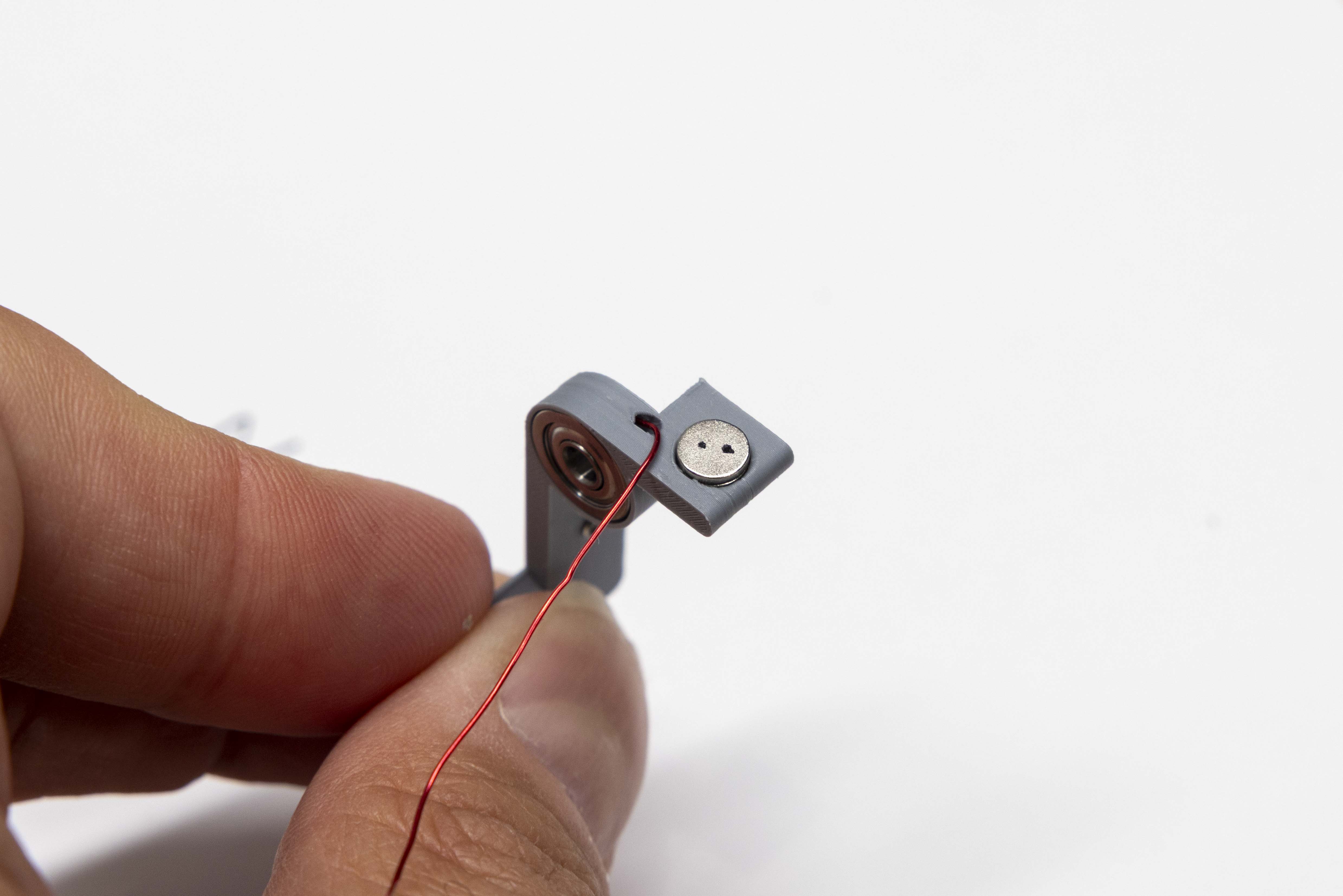
- Apply glue to the unmarked face and press the magnet into the right body magnet hole — the hole corresponding to Paddle #2's position. Press flush, dotted face outward, and wipe away any excess glue.
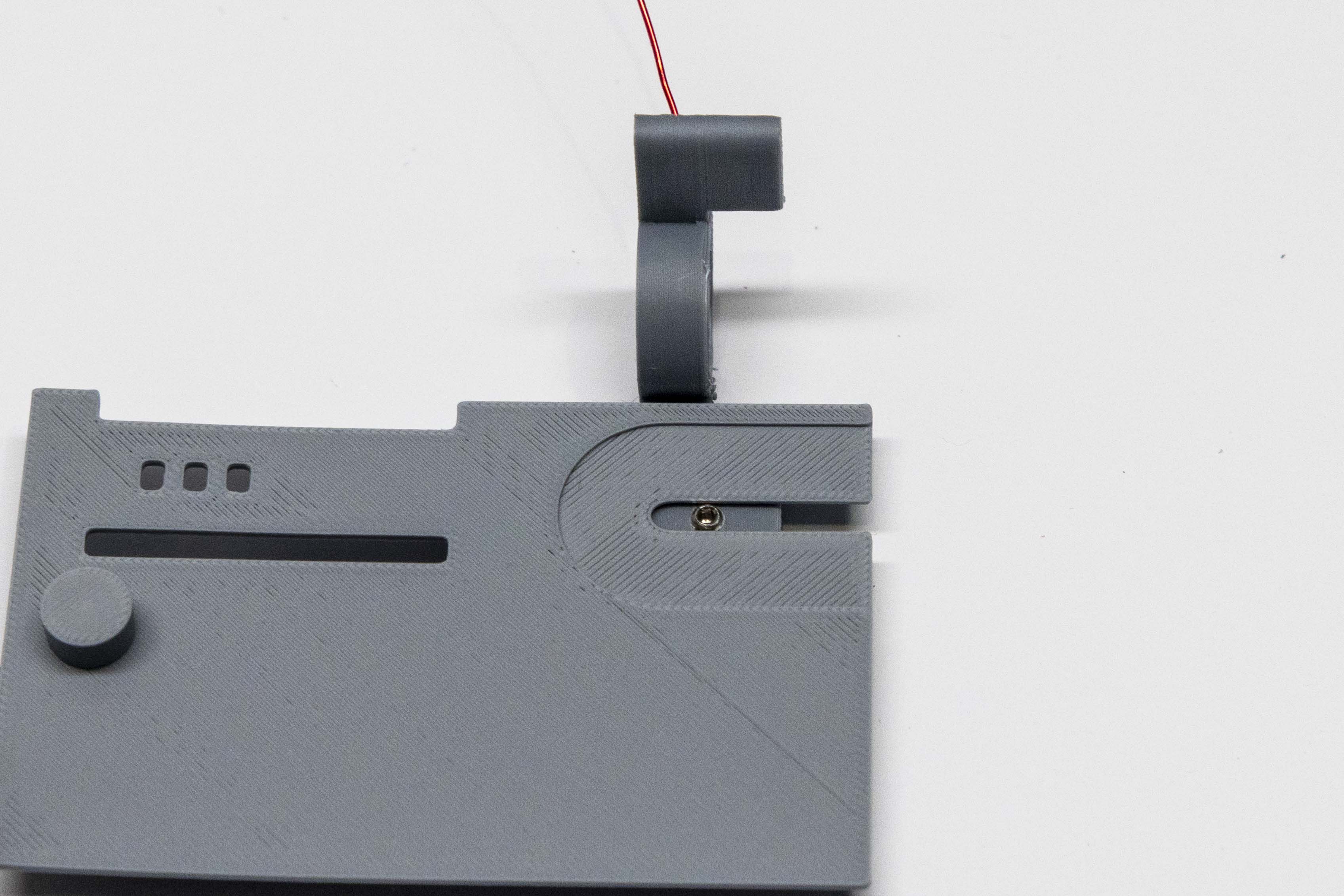
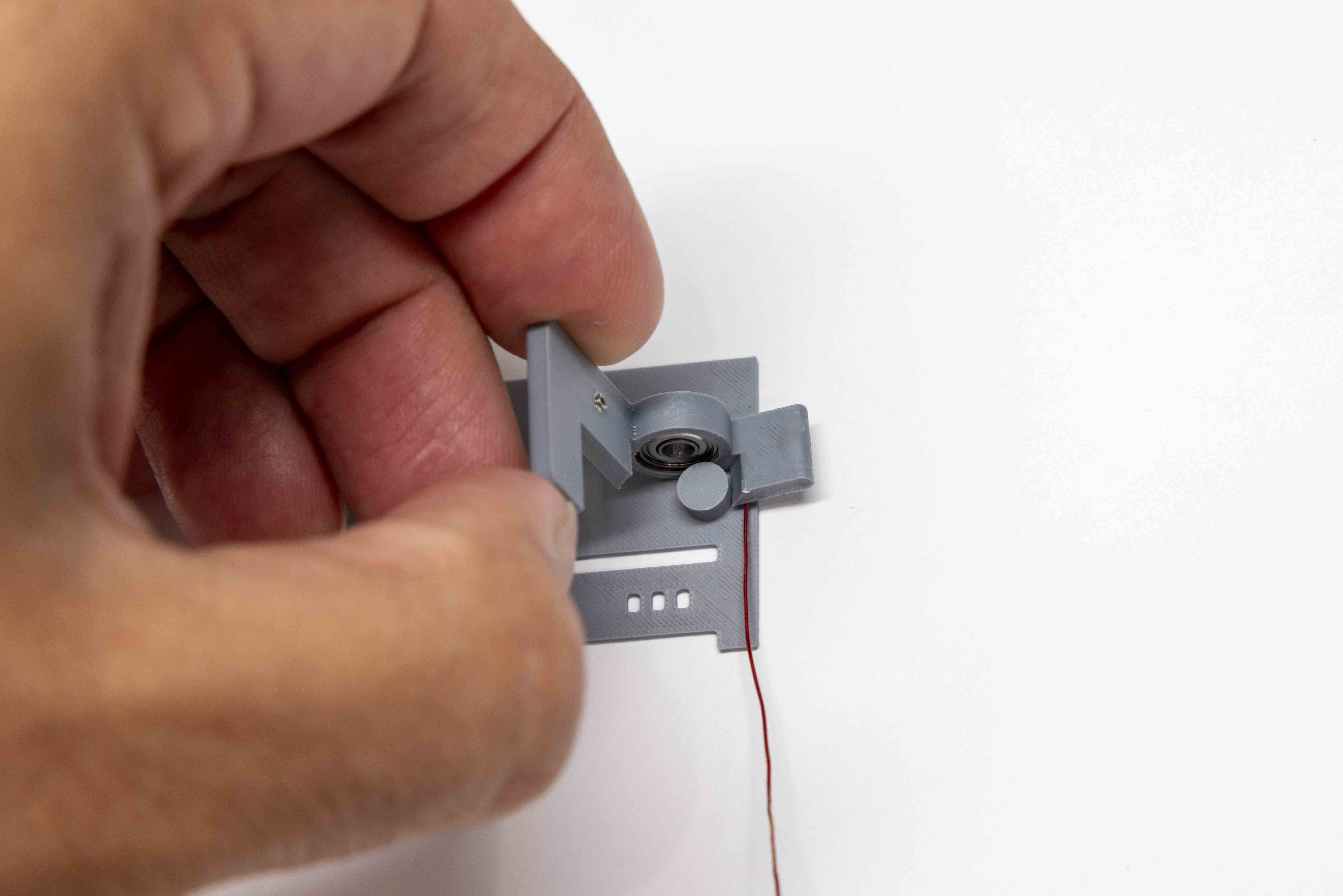
Using the travel case lid as a winding jig, form a stress-relief loop on each paddle wire. The loops reduce tension on the wire during paddle movement. Each paddle is wound differently — follow the instructions for each side carefully.
Left Paddle — 360°
- Rest the left paddle on the radius guide so the paddle arm extension faces directly toward you. The wire should be pointing toward you at the 180° position.
- Wrap the wire clockwise 360° around the radius guide nub for one full turn.
Right Paddle — 270°
- Rest the right paddle on the radius guide with the paddle handle pointing directly toward you — same orientation as the left paddle. The wire should extend to the right at the 90° position.
- Wrap the wire counter-clockwise 270° around the radius guide nub. After completing the turn, the wire should be pointing directly toward you.
Final Step — Seat the Loops
With both loops wound, press each loop firmly with your finger, pushing it as close to the paddle body as possible. This seats the wire flush and keeps the loop from interfering with assembly.
- Place the key body upright in the shipping container vise with the set screw holes facing up and accessible.
- Using the small flat screwdriver, thread each M2×3mm set screw into its pre-tapped hole by hand first to confirm it catches the threads cleanly.
- Drive each set screw in slowly until you can just see the tip beginning to protrude through the other side of the hole — then stop. Do not drive it further.
Build the mechanical stack outside the key body first, then lower the complete assembly into position as a unit.
- Insert the M2.5 shoulder bolt down through the F693ZZ flanged bearing of the left paddle (Paddle #1).
- Slide two 0.2mm shims onto the shoulder bolt, above the bearing.
- Using tweezers, position the M3 plastic sleeve over the threaded end of the bolt and thread it on carefully until it seats flush against the shoulder.
This sleeve extends the effective shoulder length of the bolt.
- Lower the right paddle (Paddle #2) onto the stack, passing its bearing down over the shoulder bolt and sleeve. The sleeve should produce a snug fit between the two paddles.
- Flip the entire stack upside down and slide two more 0.2mm shims onto the bolt below the right paddle bearing. Holding the stack upside down makes this much easier.
- Feed both paddle wires through their respective holes in the key body. While still holding the stack upside down, lower the key body down onto the stack so the shoulder bolt meets the threaded hole in the key body.
- Thread the shoulder bolt into the key body and tighten until snug. Do not overtighten.
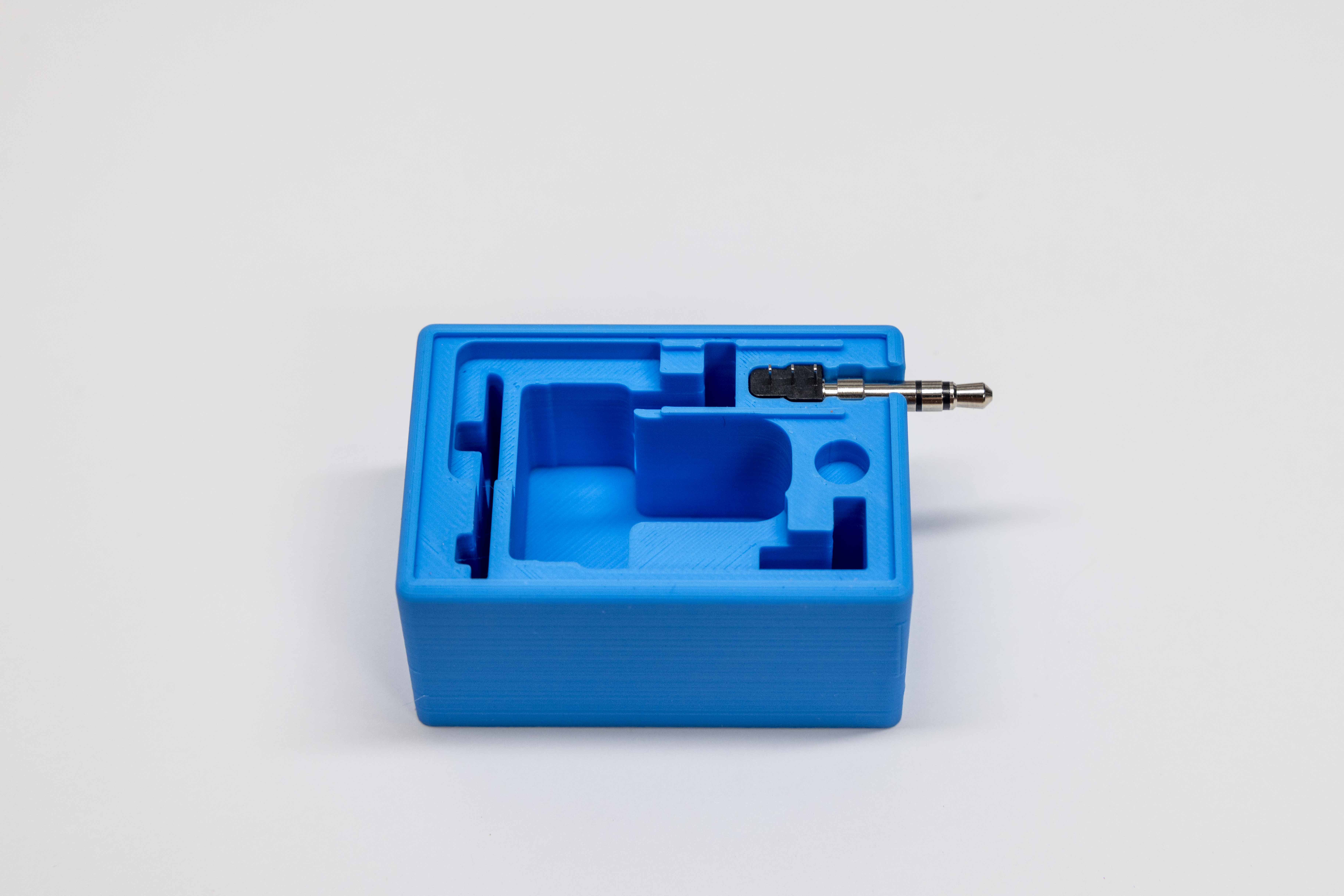
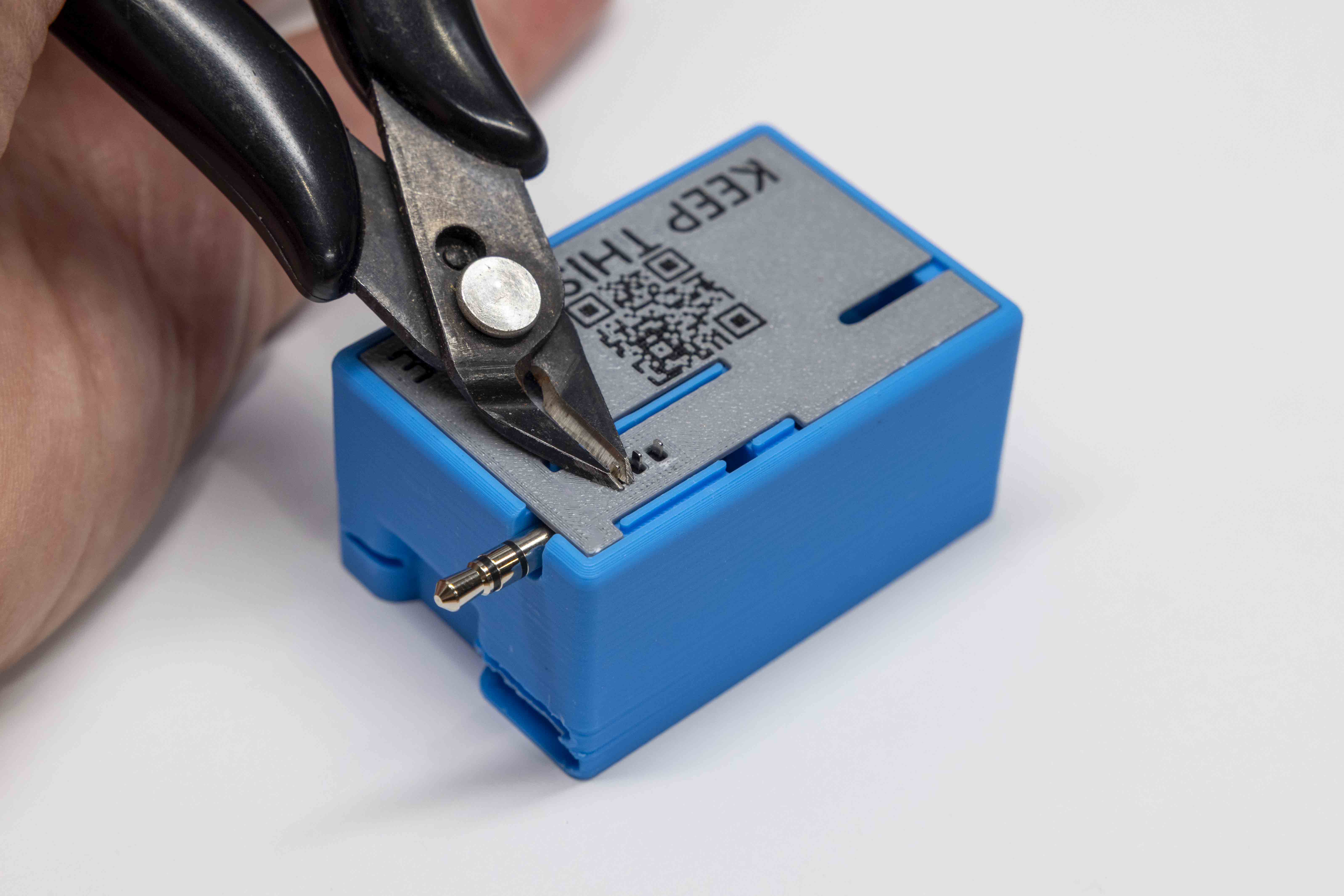
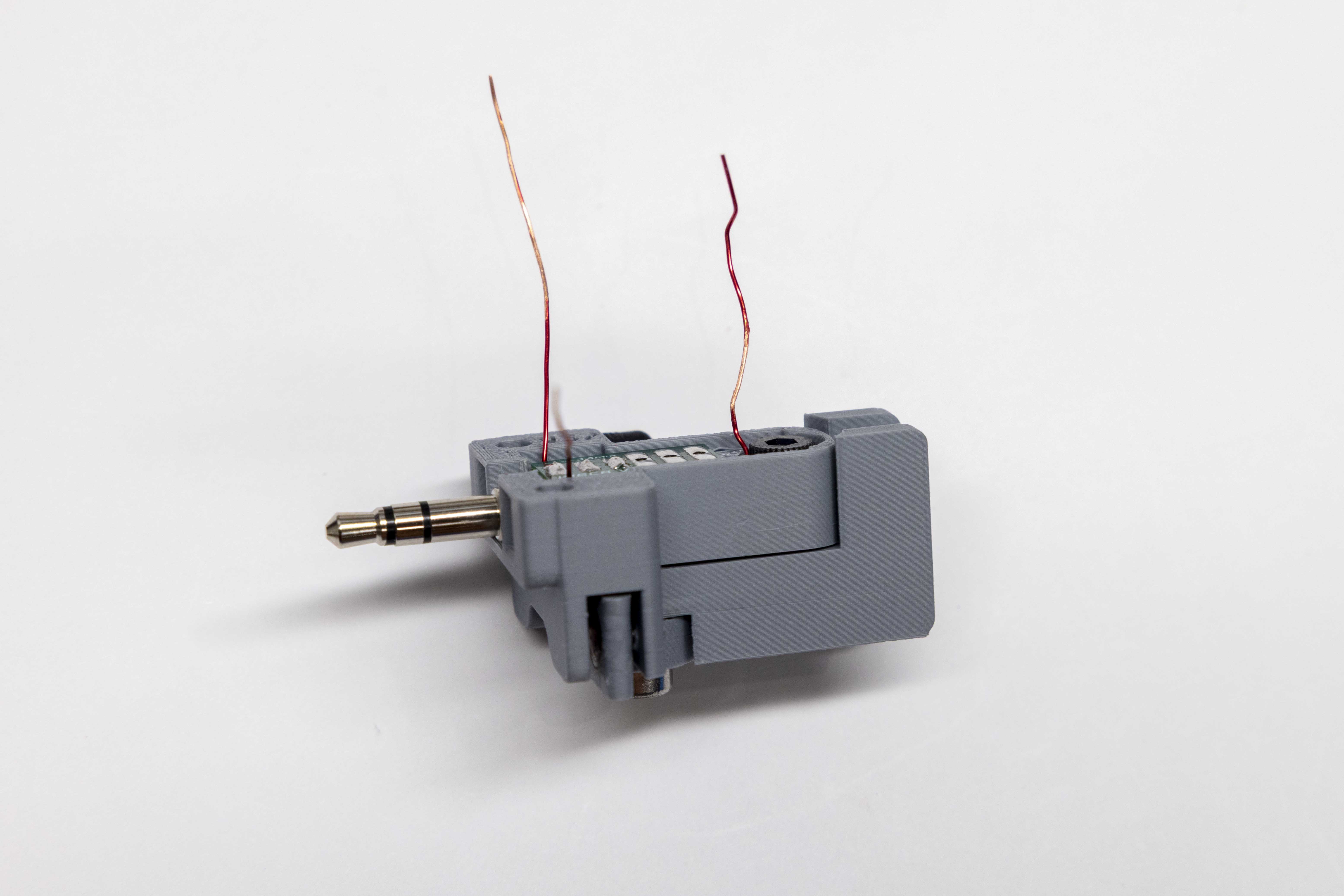
- Place the 3.5mm jack into the cutout on the shipping container. Lay the lid flat on top of the container. Note where the jack's terminals protrude through the guide holes in the lid. Using flush wire cutters, snip each terminal flush with the lid surface. Run your fingertip across the trimmed terminals — if you feel any point or protrusion, the cut was not flush and should be re-trimmed.
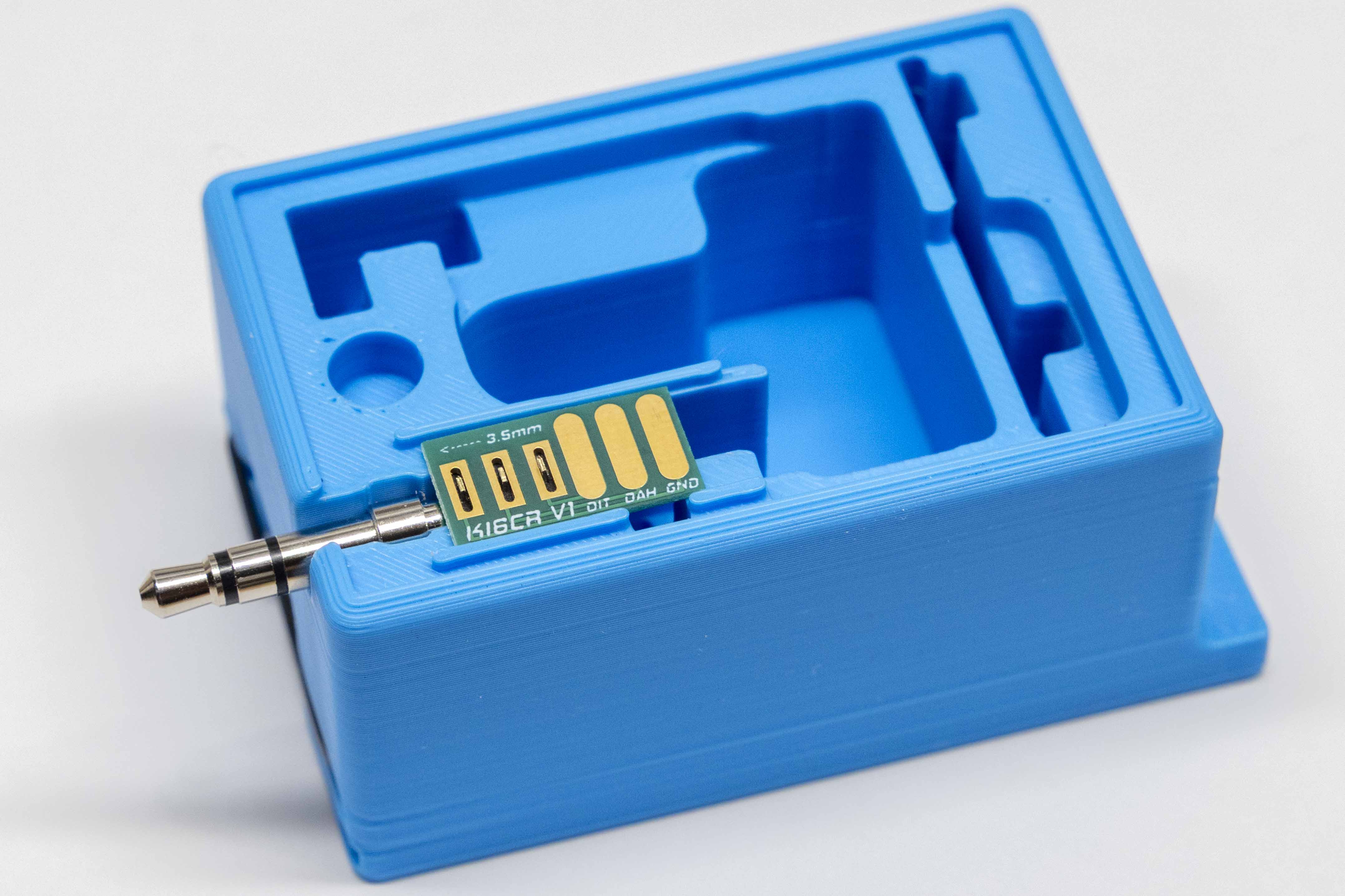
- Remove the lid. Before seating the PCB breakout board, confirm the 3.5mm jack is oriented so it points in the same direction as the arrow printed on the PCB board. Then align the board to the jack terminals using the container's alignment guides.
If the PCB does not drop in freely, use the sandpaper to gently sand both edges of the breakout board equally until it seats without force between the alignment guides.
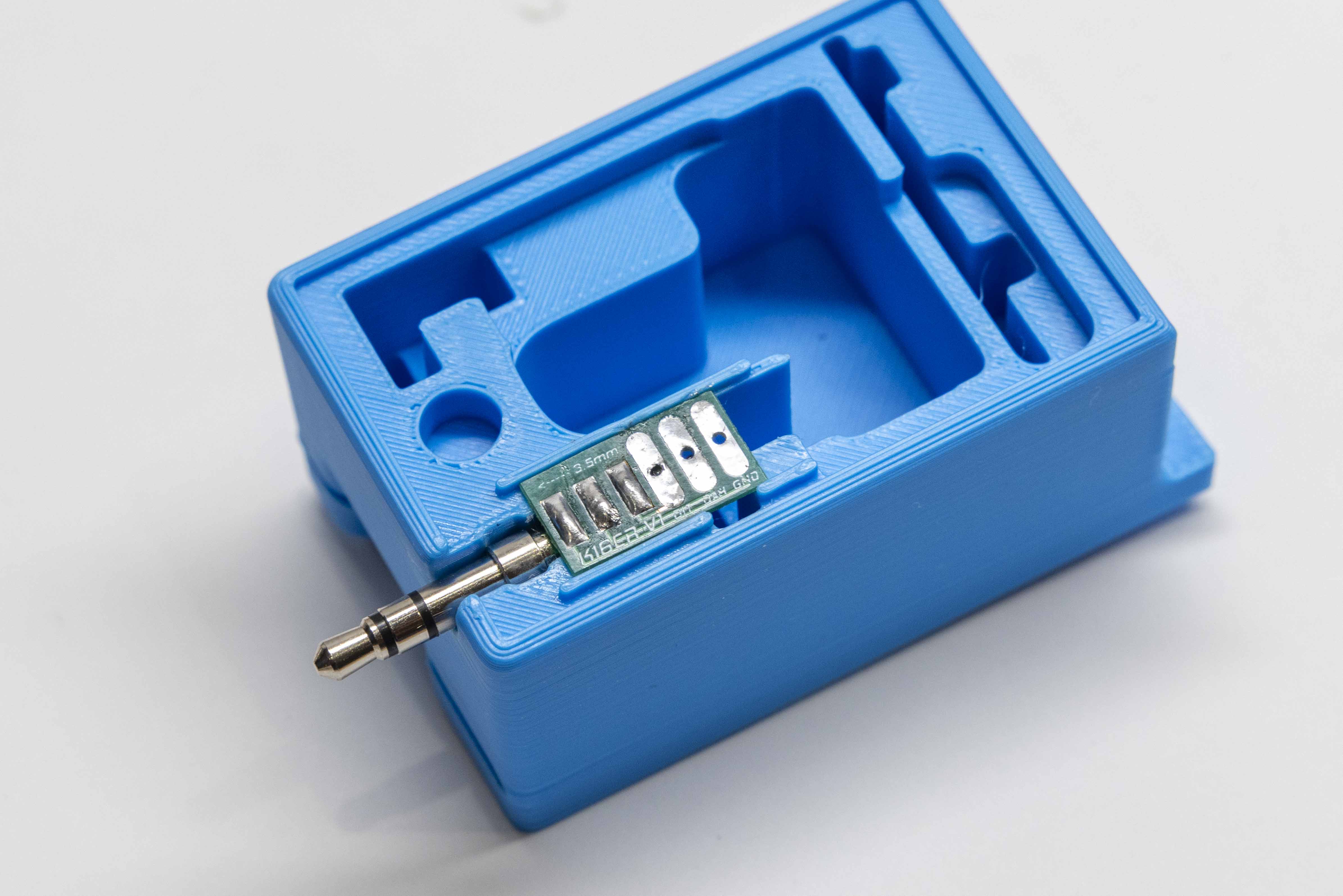
- Apply just enough solder to form a solid connection between each terminal and its corresponding PCB pad. Then apply light tinning to the signal pads on the opposite end of the PCB where the paddle wires will attach in Step 16.
- Insert the plug and PCB assembly into the CW key body. Turn the key body to view it from a profile (side) view and check whether any solder beads are visible above the key body surface. If you see any, that's okay for now — we'll determine in Step 17 whether they need to be filed down after the key is fully wired.
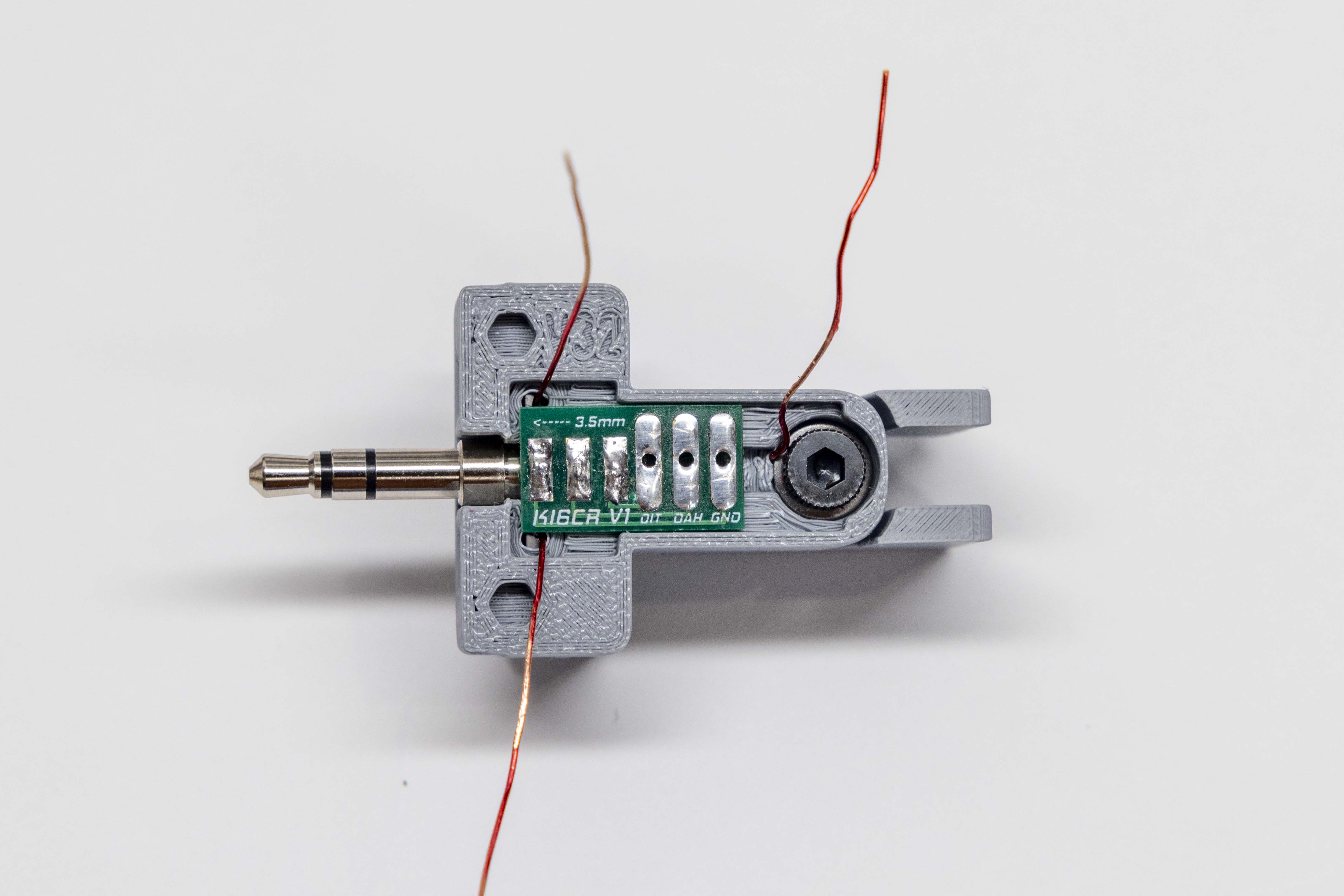
- With the PCB board seated in the key body, begin routing each paddle wire so it makes clean 90-degree turns toward its corresponding pad on the PCB breakout board. Route each wire directly to its own pad — do not allow a wire to pass over or across a neighboring pad. A wire crossing over an adjacent pad risks creating an unintended solder bridge when soldering.
- Thread each wire down through its labeled through-hole — DIT, DAH, or GND. The through-holes will hold the wires in position while you solder. Route any excess wire toward the center lug using the small channel cutout in the key body to keep it out of the way.
- Once the wires are routed the way you want them, solder each wire in place at its pad.
- With everything looking good, confirm and solder the DIT, DAH, and GND wires to their respective pads.
- Plug the key into your radio and test both paddles.
- With the key inserted into your radio, slowly turn each body set screw clockwise using the small flathead screwdriver until you hear the radio actuate. Then back the screw out 1/8 to ¼ turn to taste — find what feels right for your operating style. Note: Each set screw controls the contact point for the opposite paddle. If the key feels erratic or oversensitive, back the set screw out an additional 1/6 to 1/8 turn until the action feels clean.
- Test both paddles thoroughly and fine-tune until the key responds exactly the way you like.
- Once satisfied with the action, back the M3 shoulder bolt out slightly to relieve any tension on the assembly. Fill the shoulder bolt's threaded hole with a drop of superglue, then apply ample superglue to the entire 3.5mm plug cavity. Work quickly — superglue sets fast.
- Insert the key into your radio and make any slight positional adjustments to get it into your preferred operating position. Allow the glue to cure fully before removing the key.
- Before placing the lid, operate the key over a few sessions to confirm everything is working correctly. The lid goes on last — take the time to satisfy yourself the key performs reliably under normal operating conditions.
- Once confident everything is working correctly, lay the CW key lid on a flat surface with the tension-fit nubs facing up. Set the key body on top, aligning the male and female nubs. Press firmly and evenly until the lid seats fully — you should feel it snap into place.
